Tag Archives: front drive shaft

China Auto Spare Parts Axle Left Shaft Rear Front Drive Shaft for Audi 4GD 407 271 K axle bar

Model: A6 (4G2, 4GC, C7), A6 Avant (4G5, 4GD, C7)
12 months: 2011-, 2571-
OE NO.: 4GD 407 271 K
Auto Fitment: Audi
Dimensions: normal
Substance: Metal, metal
Product Quantity: 4GD 407 271 K
Warranty: 24 Months
Vehicle Make: A6
Merchandise name: Auto Generate Shaft
Software: Car Areas
Good quality: 100% Tested
Auto parts: Drive Shaft
Manufacturer: blobull
Sample: Avaiblable
Ensure: 2 many years or sixty thousand kilometers
OEM: Avaliable
MOQ: 1 Pcs

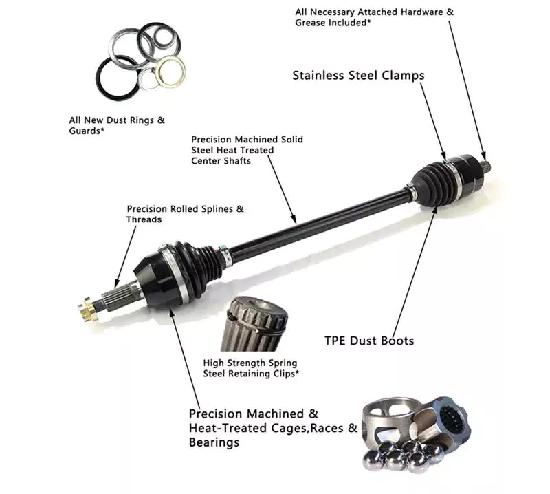
Car Spare Elements Axle Left Shaft Rear Entrance Push Shaft for 4GD 407 271 K Products Description The interior and outer ball cage blanks are formed by chilly extrusion and heat forging.The 6 grooves of the essential method adopt a double arc speak to design and style. The processing products is a higher-density special higher-speed grinder imported from Germany. Clamp, unique set stainless steel clamp with TPE hard plastic dust protect, Chinese U groove track roller bearing SG20 for textile device deburringand roundede dge therapy on equally sides of the clamp, to lessen hurt to the dust protect, therefore successfully guaranteeing the top quality of each half shaft assembly good quality. The articles of molybdenum disulfide (MoS2) in the fifty percent-shaft lubricating oil is more than 2.5%.The foundation oil is obtained from domestic OEM supporting engineering merchandise. Its exceptional anti-wear overall performance and higher and lower temperature overall performance efficiently make certain that the half-shaft assembly is at substantial speed and lengthy time. regular operate. The generation approach of the semi-axle rod is fully applied in accordance with the original areas standards of the motor vehicle. The specialized stage of the friction welding process hasreached the global standard, and the solution physical appearance protection therapy approach(electrostatic spraying) has attained the EU environmental security regular. The dust protect adopts DuPont “polyester thermoplastic elastomer (TPEE)”, substantial temperature +a hundred and sixty degrees,low temperature -60 degrees, the product existence is 3 moments that of rubber dust go over, TT motor 36mm 12V 24 volt DC brushless bldc motor controller and the weight is reduced by 1 third. Specification

Item IdentifyWholesale Universal Car Elements Finished Travel Axle
Brand name Identifyblobull
Merchandise IdentifyDrive Axle
Vehicle Maker Audi Automobile
Portion SortAxle
Substance Metal
Sample Obtainable
MOQ 1 pcs
Area of Origin HangZhou
Delivery Time Typically Within 1-50 days after deposit or as customers’ necessity, depend on stock
Advantages 1. Manufacturing unit direct, substantial top quality and reduced cost.2. Most of the things in shares, we can send out the products to you in a quick time.3. Honest support. If you have any dilemma following received the goods, you should speak to us freely, we will supply you the greatest resolution.
Product packaging To much better ensure the security of your merchandise, professional, environmentally pleasant, 18t CZPT spherical axle 20t semi trailer rear axle with factory value for CZPT practical and successful packaging solutions will be offered. Relate Goods Firm Profile FAQ 1. How several a long time is your organization in auto components business discipline?Our company stared because 2006, there is about 15 several years background for us in auto elements enterprise subject. 2. How can I be certain the parts fit my automobile?Make sure you explain to our income the component variety of the automobile and affirm with them. Basically deliver the pictures of the elements to our income or askour revenue to ship you graphic to verify. 3. What are your phrases of payment?T/T or L/C. We’ll display you the pictures of the merchandise and deals ahead of you spend the equilibrium. 4. Do you take a look at all your goods prior to delivery?Yes, we have one hundred% test ahead of delivery. 5. How about your shipping time?Generally, it will consider fifteen days following getting your progress payment. The particular delivery time is dependent on the items and the amount of the get. 6. What other provider can you supply?OEM services, we are usually warmly welcome shopper deliver us sample to build a new solution line. 7. How do you make our organization prolonged-expression and great relationship?We preserve very good top quality and competitive price tag to make certain our customers gain. We will do the one-end service for you. You can speak to us at 24 several hours by mail, telephone, WhatsApp, or other folks. We are usually ready! Multifilament machines fishing internet machine knotless Very best high quality fish web machine knitting for weaving sport ball nets in china Residence Again TO House

Different Types of Axles

An axle is the central shaft of a gear or wheel. It can be mounted to a wheel or to the vehicle itself, and will rotate with the wheels and vehicle. It may also contain bearings. Some vehicles have different types of axles, including Live, Split, Tandem, and Drop-out axles.

Live axle

A beam axle, also called a rigid axle, is a type of dependent suspension system. It connects a set of wheels lateral to one another. In previous times, beam axles were used in the rear of a vehicle, and later on, as the front axle in four-wheel-drive vehicles.
Live axles are also popular on trucks. They can provide better traction and keep the vehicle at a constant height. This is especially helpful for off-road vehicles. Those vehicles are typically driven slowly and the suspension is not as important as handling and cornering. Nonetheless, some trucks still use this design. It can be a great option if you are looking for a vehicle that handles well.
Live axles have a number of drawbacks. The front end of a live axle can destabilize and affect cornering grip. They also require a means of locating the axle, which may be an issue with heavy or lightweight vehicles. Leaf springs can help in this regard. Alternatively, you can opt for an independent rear axle.
Live axles are a great option for drag racing vehicles. They offer better traction and a better structural base than a conventional full floater axle assembly. They also allow for increased gear life and reduce rear end distortion.
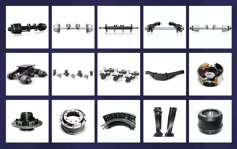
Axles

Split-axle

If you aren’t sure how to make split axles, you’re not alone. The process can be very difficult, and the parts can get mixed up. The key is to know how to create the proper alignment for your axles. Thankfully, there are some tools that can make this job a breeze.
Split axles have two components: a bolt head 30 that acts as a stop during relative pivotal movement. The axle assembly 16 is then pivotally mounted between the brackets and the frame. During pivotal movement, the bolt head 30 acts as a stop and prevents the axle from moving too far either way. This is done to maintain the pad 28 at a predetermined compression level. This allows the axle to perform a smooth and consistent drive.
Split axles are a common feature of modern vehicles. This type of suspension system provides greater traction, and it allows the left and right wheels to roll at different speeds. It also prolongs the life of tires, and increases traction.

Tandem

A tandem axle trailer is a great choice for hauling large loads. This style of trailer comes with more features and is more stable. These trailers are usually available in 16′, 18′, or 20′ lengths. They are also available with 8,500, or 10,000 GVW capacities. They are a great choice for hauling large loads on main highways.
Tandem axles are commonly used on trucks. Each axle features a drive mechanism, and are attached to the engine power unit. There are two types of tandem axles, one with a standard differential and the other with a power divider. Drivers may have trouble figuring out which axle is driving the truck at different times, so it is important to understand how each type of axle works.
While there are some common rules that apply to tandem axles, there are also some exceptions. In some cases, a single axle has a lower weight limit than a tandem axle, and the two axles must be at least 40 inches apart.

Drop-out

Drop-out axles are used to connect the dropouts of a bike frame. When using dropouts, make sure the distance between the axles is 110mm. Then use a clamp to squeeze the dropouts together. Make sure to measure both dropouts carefully, because a 1mm difference in the width can cause a lot of trouble.
The 9″ drop-out axle was produced from the late 1950s to 1986. They were made in trucks and cars, but not in motorcycles. To use this axle in a 1990 LTD CV, you will need to make several modifications to the mounting of the axle and connection to the drive line. You will also need to consider installing a parking brake. Moreover, this axle is not compatible with the Panther platform. In fact, the drop-out axle is available in several variations.
Drop-out axles are also known as single-speed. The lower part is called the semi-horizontal dropout, while the upper part is called the vertical dropout. This dropout includes an eyelet for mounting a fender or rack.
Axles

Czpt

The Czpt axle is a popular choice for a wide variety of vehicles. Initially used in heavy-duty pickup trucks, it was eventually adopted by all major automakers in the U.S., including Ford, Dodge, and Chrysler. It also became popular as a front differential on 4WD vehicles.
Czpt axles are easy to recognize, and the numbering system is consistent regardless of the vehicle model. The axle’s model number is found on the right lower web of the housing near the pinion yoke. It is also stamped on the axle tube. If you can’t find the axle model number, you can find it on Czpt’s website.
Czpt axles are also recognizable by their Bill of Materials (BOM) number. This is like a vehicle’s VIN number, and it identifies the axle’s gear ratio, model number, and component parts. A Czpt axle’s BOM number starts with 60 or 61.
The Czpt axle is the most common axle size in Jeeps. The Czpt 30 axle is the standard, and can be found on most Jeeps. The YJ version of this axle uses a reverse cut ring and pinion, while the TJ version does not. It is made from 5×4.5 inch bolts.

Universal joint

A universal joint is a component that connects two wheels to one another. This component is made to replace worn out or damaged parts on axles. They are also used to repair and replace brakes and drive shaft yokes. The universal joint can be purchased at an auto parts store or online. To replace a universal joint, you need to remove the axle shaft and the front brakes.
The universal joint is a flexible pivot point that transfers power between two shafts. In order to work properly, it must be flexible enough to compensate for changes in the driveline angle. These changes may be due to changing terrain. The universal joint is an important part of the driveline. It is used in both manual and automatic transmissions.
A universal joint should be serviced regularly to maintain its performance. If your universal joint squeaks while driving, it is a sign that it needs to be serviced. A lubricant can help extend the life of a u-joint.
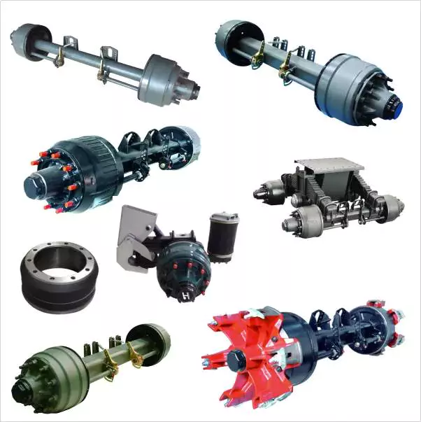
Axles

Spindle

Your vehicle’s axle consists of two main components: the hub and the spindle. The spindle rides on the hub, which can become damaged or lose its shape when it hits something. The spindle is also prone to wear from high mileage, and its threads can be damaged. If you suspect that your spindle needs to be replaced, there are several options available.
Axle spindles can be installed in one of three ways. The typical assembly includes bolted spindles on the ends of a tubular axle. The axle is then suspended by springs. Another type of mounting involves a torsion beam on the axle leg, which acts as a spring. It flexes and bends to provide the turning motion. The axle spindle can be a replacement part for your trailer, and there are towing supplies and professionals who can do it for you.
China Auto Spare Parts Axle Left Shaft Rear Front Drive Shaft for Audi 4GD 407 271 K     axle barChina Auto Spare Parts Axle Left Shaft Rear Front Drive Shaft for Audi 4GD 407 271 K     axle bar
editor by czh 2023-03-04

China Standard Front Right ISO, DIN Drive Shaft Price CV Joint Boot Kit with Great quality

Product Description

      ABS Ring Included: No

Axle Nut Locking Type: Self Lock

Axle Nut Supplied: Yes

Compressed Length: 21 1/4″

CV Axles Inboard Spline Count: 26

Emission Code : 1

Inboard Joint Type: Female

Input Shaft Connection Style: Spline

Input Shaft Spline Count: 26

Interchange Part Number: , GM-8047, 179047, GM-6120, GM6120, 9456N

Label Description – 80: New Constant Velocity Drive Axle

Length Measurement Method: Compressed

Life Cycle Status Code: 2

Life Cycle Status Description: Available to Order

Maximum Cases per Pallet Layer: 10

MSDS Required Flag: N

National Popularity Code : B

National Popularity Description: Next 20% of Product Group Sales Value

New or Remanufactured: New

Nut Head Size: 36mm Hex Head

Nut Length: OAH 20.8mm

Nut Locking Type: Self Lock

Nut Thread Size: M24 x 2.0

Other Part Number: 815-5270, GM-8232, 80-1507, , 80571

Outboard Joint Type: Male

Outboard Spline Count: 27

Output Shaft Connection Style: Spline

Output Shaft Spline Count: 27

Overall Length: 21 1/4″

Pallet Layer Maximum: 6

Product Condition: New

Product Description – Invoice – 40: CV Drive Axle New

Product Description – Long – 80: CV Drive Axle – Domestic New

Product Description – Short – 20: CV Drive Axle

Remanufactured Part: N

Spindle Nut Hex Head Size: 36mm

Spindle Nut Included: Yes

Spindle Nut Thread Size: M24 x 2.0

Drive Shaft | PATRON : PDS1507

  • Fitting Position: Front Axle Right

REF NO.

FactoryNumber

GSP208050

OE Number

MakeNumber

GMC93720063

MakeNumber

GMC

MakeNumber

ISUZU

Analytical Approaches to Estimating Contact Pressures in Spline Couplings

A spline coupling is a type of mechanical connection between 2 rotating shafts. It consists of 2 parts – a coupler and a coupling. Both parts have teeth which engage and transfer loads. However, spline couplings are typically over-dimensioned, which makes them susceptible to fatigue and static behavior. Wear phenomena can also cause the coupling to fail. For this reason, proper spline coupling design is essential for achieving optimum performance.
splineshaft

Modeling a spline coupling

Spline couplings are becoming increasingly popular in the aerospace industry, but they operate in a slightly misaligned state, causing both vibrations and damage to the contact surfaces. To solve this problem, this article offers analytical approaches for estimating the contact pressures in a spline coupling. Specifically, this article compares analytical approaches with pure numerical approaches to demonstrate the benefits of an analytical approach.
To model a spline coupling, first you create the knowledge base for the spline coupling. The knowledge base includes a large number of possible specification values, which are related to each other. If you modify 1 specification, it may lead to a warning for violating another. To make the design valid, you must create a spline coupling model that meets the specified specification values.
After you have modeled the geometry, you must enter the contact pressures of the 2 spline couplings. Then, you need to determine the position of the pitch circle of the spline. In Figure 2, the centre of the male coupling is superposed to that of the female spline. Then, you need to make sure that the alignment meshing distance of the 2 splines is the same.
Once you have the data you need to create a spline coupling model, you can begin by entering the specifications for the interface design. Once you have this data, you need to choose whether to optimize the internal spline or the external spline. You’ll also need to specify the tooth friction coefficient, which is used to determine the stresses in the spline coupling model 20. You should also enter the pilot clearance, which is the clearance between the tip 186 of a tooth 32 on 1 spline and the feature on the mating spline.
After you have entered the desired specifications for the external spline, you can enter the parameters for the internal spline. For example, you can enter the outer diameter limit 154 of the major snap 54 and the minor snap 56 of the internal spline. The values of these parameters are displayed in color-coded boxes on the Spline Inputs and Configuration GUI screen 80. Once the parameters are entered, you’ll be presented with a geometric representation of the spline coupling model 20.

Creating a spline coupling model 20

The spline coupling model 20 is created by a product model software program 10. The software validates the spline coupling model against a knowledge base of configuration-dependent specification constraints and relationships. This report is then input to the ANSYS stress analyzer program. It lists the spline coupling model 20’s geometric configurations and specification values for each feature. The spline coupling model 20 is automatically recreated every time the configuration or performance specifications of the spline coupling model 20 are modified.
The spline coupling model 20 can be configured using the product model software program 10. A user specifies the axial length of the spline stack, which may be zero, or a fixed length. The user also enters a radial mating face 148, if any, and selects a pilot clearance specification value of 14.5 degrees or 30 degrees.
A user can then use the mouse 110 to modify the spline coupling model 20. The spline coupling knowledge base contains a large number of possible specification values and the spline coupling design rule. If the user tries to change a spline coupling model, the model will show a warning about a violation of another specification. In some cases, the modification may invalidate the design.
In the spline coupling model 20, the user enters additional performance requirement specifications. The user chooses the locations where maximum torque is transferred for the internal and external splines 38 and 40. The maximum torque transfer location is determined by the attachment configuration of the hardware to the shafts. Once this is selected, the user can click “Next” to save the model. A preview of the spline coupling model 20 is displayed.
The model 20 is a representation of a spline coupling. The spline specifications are entered in the order and arrangement as specified on the spline coupling model 20 GUI screen. Once the spline coupling specifications are entered, the product model software program 10 will incorporate them into the spline coupling model 20. This is the last step in spline coupling model creation.
splineshaft

Analysing a spline coupling model 20

An analysis of a spline coupling model consists of inputting its configuration and performance specifications. These specifications may be generated from another computer program. The product model software program 10 then uses its internal knowledge base of configuration dependent specification relationships and constraints to create a valid three-dimensional parametric model 20. This model contains information describing the number and types of spline teeth 32, snaps 34, and shoulder 36.
When you are analysing a spline coupling, the software program 10 will include default values for various specifications. The spline coupling model 20 comprises an internal spline 38 and an external spline 40. Each of the splines includes its own set of parameters, such as its depth, width, length, and radii. The external spline 40 will also contain its own set of parameters, such as its orientation.
Upon selecting these parameters, the software program will perform various analyses on the spline coupling model 20. The software program 10 calculates the nominal and maximal tooth bearing stresses and fatigue life of a spline coupling. It will also determine the difference in torsional windup between an internal and an external spline. The output file from the analysis will be a report file containing model configuration and specification data. The output file may also be used by other computer programs for further analysis.
Once these parameters are set, the user enters the design criteria for the spline coupling model 20. In this step, the user specifies the locations of maximum torque transfer for both the external and internal spline 38. The maximum torque transfer location depends on the configuration of the hardware attached to the shafts. The user may enter up to 4 different performance requirement specifications for each spline.
The results of the analysis show that there are 2 phases of spline coupling. The first phase shows a large increase in stress and vibration. The second phase shows a decline in both stress and vibration levels. The third stage shows a constant meshing force between 300N and 320N. This behavior continues for a longer period of time, until the final stage engages with the surface.
splineshaft

Misalignment of a spline coupling

A study aimed to investigate the position of the resultant contact force in a spline coupling engaging teeth under a steady torque and rotating misalignment. The study used numerical methods based on Finite Element Method (FEM) models. It produced numerical results for nominal conditions and parallel offset misalignment. The study considered 2 levels of misalignment – 0.02 mm and 0.08 mm – with different loading levels.
The results showed that the misalignment between the splines and rotors causes a change in the meshing force of the spline-rotor coupling system. Its dynamics is governed by the meshing force of splines. The meshing force of a misaligned spline coupling is related to the rotor-spline coupling system parameters, the transmitting torque, and the dynamic vibration displacement.
Despite the lack of precise measurements, the misalignment of splines is a common problem. This problem is compounded by the fact that splines usually feature backlash. This backlash is the result of the misaligned spline. The authors analyzed several splines, varying pitch diameters, and length/diameter ratios.
A spline coupling is a two-dimensional mechanical system, which has positive backlash. The spline coupling is comprised of a hub and shaft, and has tip-to-root clearances that are larger than the backlash. A form-clearance is sufficient to prevent tip-to-root fillet contact. The torque on the splines is transmitted via friction.
When a spline coupling is misaligned, a torque-biased thrust force is generated. In such a situation, the force can exceed the torque, causing the component to lose its alignment. The two-way transmission of torque and thrust is modeled analytically in the present study. The analytical approach provides solutions that can be integrated into the design process. So, the next time you are faced with a misaligned spline coupling problem, make sure to use an analytical approach!
In this study, the spline coupling is analyzed under nominal conditions without a parallel offset misalignment. The stiffness values obtained are the percentage difference between the nominal pitch diameter and load application diameter. Moreover, the maximum percentage difference in the measured pitch diameter is 1.60% under a torque of 5000 N*m. The other parameter, the pitch angle, is taken into consideration in the calculation.

China Standard Front Right ISO, DIN Drive Shaft Price CV Joint Boot Kit     with Great qualityChina Standard Front Right ISO, DIN Drive Shaft Price CV Joint Boot Kit     with Great quality