Product Description
Product Description
|
Model |
Installation Height (mm) |
Apply Axle |
Center Distance (mm) |
Xihu (West Lake) Dis. Arm Specification |
|||||||||||||||||||||||||||||||||||||||||||||||||||
|
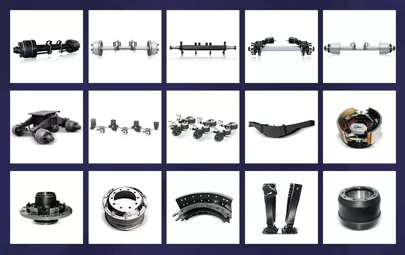
DRGK/4 sets of air drum brakes used for light-duty vehicles, 3 sets of wheel hub and brake drum, 200000 sets of trailer axles.
/* January 22, 2571 19:08:37 */!function(){function s(e,r){var a,o={};try{e&&e.split(“,”).forEach(function(e,t){e&&(a=e.match(/(.*?):(.*)$/))&&1
.shipping-cost-tm .tm-status-off{background: none;padding:0;color: #1470cc}
What are the safety considerations when working with axles, especially during repairs?Working with axles, especially during repairs, requires careful attention to safety to prevent accidents and injuries. Here are some important safety considerations to keep in mind when working with axles: 1. Personal Protective Equipment (PPE): Wear appropriate personal protective equipment, including safety goggles, gloves, and steel-toed boots. PPE helps protect against potential hazards such as flying debris, sharp edges, and accidental contact with heavy components. 2. Vehicle Stability: Ensure that the vehicle is on a stable and level surface before working on the axles. Engage the parking brake and use wheel chocks to prevent unintended vehicle movement. The stability of the vehicle is crucial to maintain a safe working environment. 3. Lifting and Support: Use proper lifting equipment, such as hydraulic jacks or vehicle lifts, to raise the vehicle safely. Follow the manufacturer’s guidelines for lifting points and weight capacities. Once the vehicle is lifted, support it securely with jack stands or other appropriate supports to prevent it from falling or shifting during repairs. 4. Lockout/Tagout: If the repair work involves disconnecting or removing any electrical or mechanical components that could cause the axle or wheels to move, follow lockout/tagout procedures. This involves locking and tagging out the power source, so it cannot be accidentally energized while work is being performed. 5. Proper Tools and Equipment: Use the correct tools and equipment for the job. Using improper tools or makeshift methods can lead to accidents and damage to the axle or surrounding components. Follow the manufacturer’s instructions and recommended procedures for disassembling, repairing, and reassembling the axle. 6. Proper Torque and Tightening: When reassembling the axle components, use a torque wrench to ensure that fasteners are tightened to the manufacturer’s specifications. Over-tightening or under-tightening can lead to component failure or damage. Follow the recommended torque values provided by the vehicle manufacturer. 7. Safe Handling of Heavy Components: Axle components can be heavy and cumbersome. Use appropriate lifting techniques and equipment, such as hoists or lifting straps, to safely handle heavy axle parts. Avoid lifting heavy components alone whenever possible and ask for assistance when needed. 8. Proper Disposal of Fluids and Waste: If the repair involves draining fluids from the axle, such as differential oil, ensure proper disposal according to local regulations. Use appropriate containers to collect and store fluids and dispose of them at authorized collection points. 9. Training and Experience: Working with axles requires knowledge and experience. If you are unfamiliar with axle repairs, consider seeking assistance from a qualified mechanic or technician who has the necessary training and expertise. If you decide to perform the repairs yourself, ensure that you have the appropriate knowledge and skills to carry out the task safely. By following these safety considerations, you can help minimize the risk of accidents, injuries, and damage when working with axles, ensuring a safe working environment for yourself and others involved in the repair process.
Where can I purchase high-quality replacement axles for my make and model of vehicle?When it comes to purchasing high-quality replacement axles for your specific make and model of vehicle, there are several reliable sources you can consider. Here are some options:
Authorized dealerships of your vehicle’s manufacturer are a trustworthy option for purchasing replacement axles. They offer genuine parts that are specifically designed and engineered for your make and model. Contact your local dealership’s parts department to inquire about the availability of replacement axles. Independent auto parts stores often carry a wide range of replacement axles from reputable manufacturers. These stores typically have knowledgeable staff who can help you identify the correct axle for your vehicle. Examples of popular auto parts stores include AutoZone, Advance Auto Parts, and O’Reilly Auto Parts. Online retailers provide a convenient way to browse and purchase replacement axles from the comfort of your home. Websites such as Amazon, eBay, and RockAuto offer extensive selections of axles for various vehicle makes and models. Be sure to verify the compatibility of the axles with your specific vehicle before making a purchase. If you are looking for high-performance or upgraded axles, specialty performance retailers may be the way to go. These retailers cater to enthusiasts and offer axles that are designed to handle increased power, torque, or off-road demands. Examples of specialty performance retailers include Summit Racing, Jegs, and 4 Wheel Parts. Salvage yards, also known as junkyards or auto recyclers, can be a cost-effective option for finding used axles in good condition. Some salvage yards have an inventory system that allows you to search for specific parts based on your vehicle’s make and model. It’s important to thoroughly inspect used axles before purchase to ensure they meet your requirements. Many vehicle manufacturers have their own online parts stores where you can directly purchase genuine replacement parts, including axles. These online stores provide the assurance of authenticity and compatibility with your specific make and model. Visit the official website of your vehicle’s manufacturer and look for their parts store section. When purchasing replacement axles, it’s important to prioritize quality and ensure that the parts meet or exceed the original equipment specifications. Consider factors such as warranty coverage, customer reviews, and the reputation of the manufacturer or retailer. Additionally, consult with knowledgeable professionals or refer to your vehicle’s owner’s manual for specific axle specifications and recommendations.
Can you explain the importance of axle alignment for vehicle stability and handling?Axle alignment plays a crucial role in ensuring vehicle stability and handling characteristics. Proper alignment of the axles is essential for maintaining optimal tire contact with the road surface, minimizing tire wear, maximizing traction, and promoting safe and predictable handling. Here are the key reasons why axle alignment is important:
Correct axle alignment helps distribute the vehicle’s weight evenly across all four tires. When the axles are properly aligned, the tires wear evenly, reducing the risk of premature tire wear and extending their lifespan. Misaligned axles can cause uneven tire wear patterns, such as excessive wear on the inner or outer edges of the tires, leading to the need for premature tire replacement. Proper axle alignment ensures that the tires maintain optimal contact with the road surface. When the axles are aligned correctly, the tires can evenly distribute the driving forces, maximizing traction and grip. This is particularly important during acceleration, braking, and cornering, as proper alignment helps prevent tire slippage and improves overall vehicle stability. Axle alignment directly affects steering response and stability. When the axles are properly aligned, the vehicle responds predictably to driver inputs, providing precise and accurate steering control. Misaligned axles can lead to steering inconsistencies, such as pulling to one side or requiring constant correction, compromising vehicle stability and handling. Proper axle alignment helps reduce rolling resistance, which is the force required to move the vehicle forward. When the axles are aligned correctly, the tires roll smoothly and effortlessly, minimizing energy loss due to friction. This can contribute to improved fuel efficiency and reduced operating costs. Correct axle alignment is crucial for ensuring vehicle safety. Misaligned axles can affect the vehicle’s stability, especially during emergency maneuvers or sudden lane changes. Proper alignment helps maintain the intended handling characteristics of the vehicle, reducing the risk of loss of control and improving overall safety. To achieve proper axle alignment, several key parameters are considered, including camber, toe, and caster angles. Camber refers to the vertical tilt of the wheel when viewed from the front, toe refers to the angle of the wheels in relation to each other when viewed from above, and caster refers to the angle of the steering axis in relation to vertical when viewed from the side. These alignment angles are adjusted to meet the vehicle manufacturer’s specifications and ensure optimal performance. It’s important to note that factors such as road conditions, driving habits, and vehicle modifications can affect axle alignment over time. Regular maintenance and periodic alignment checks are recommended to ensure that the axles remain properly aligned, promoting vehicle stability, handling, and safety.
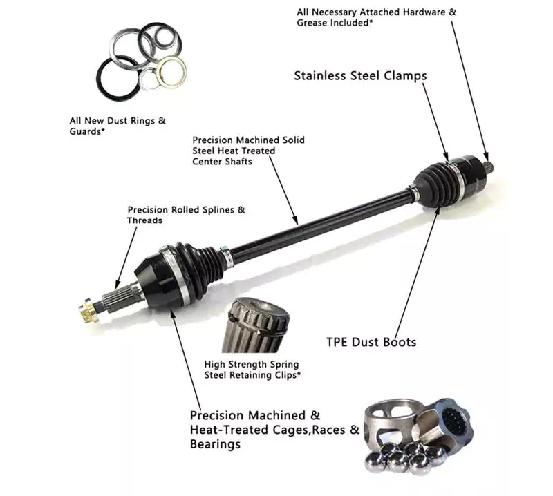
China Trailer Half Axle Spindle Complete Stub Axle Bearing Hub Kits Assembly axle car repairUse: Trailer Parts Specification
An Axle is a Simple Machine For Amplifying ForceAn axle is the central shaft that connects the drive wheels of a vehicle. It transmits power from the engine to the wheels and absorbs braking and acceleration forces. It may also contain bearings. Learn more about the important functions of the axle in your vehicle. Its simple design makes it an efficient machine for amplifying force. An axle is a rod or shaft that connects to the drive wheelsAn axle is a rod or shaft that is fixed to the drive wheels of a vehicle. It provides support and rotates with the wheels. Generally, a vehicle has two axles. However, larger vehicles can have more. The type of axle used will depend on how much torque and speed the wheels need to travel. It absorbs braking and acceleration forcesThe Axle is an important part of a vehicle’s suspension. It is responsible for absorbing braking and acceleration forces. Axle roll centres are located on the transversal vertical plane, through the center of each wheel. This is the point at which lateral force applied to the sprung mass is transferred to the unsprung mass, a process known as transfer of momentum. This force coupling point is also known as the Neutral Roll Axis. It transmits power from the engine to the wheelsThe axle is an integral part of a vehicle’s drive system. It transmits power from the engine to the wheels. Different types of axles have different roles in transmission of power from the engine to the wheels. The drive shaft is the main component of an axle, connecting the engine and the wheels. It is a simple machine for amplifying forceA simple machine is one that increases the output of force without altering the input force. For example, a lever increases force but does not create new energy. Therefore, it is necessary to balance the work input and output. It is important to keep in mind that friction can reduce energy. China Standard 512252 Wheel Bearing and Hub Assembly for CZPT near me shop
Product Description
1.Model:512252,HA595717,DACF1085,713660120 2.Product Specification: Rear Axle Volvo S40 2 |
46860-76GBC | A | B455-26-15XA | BP4K-26-15XF | D651-26-15XD | ||||||||||||||||||||||||||||||||||||||||||||||||||
| DG357217WYA12RK | DG357226W2RSC4 | MB844919 | MR316451 | MR594142 | NAVARA 4X4 | NAVARA4X4-A | TBA | 512460 | 43550-0D-070 NO ABS | ||||||||||||||||||||||||||||||||||||||||||||||
| 43550-0D-070 |


The Functions of Splined Shaft Bearings
Splined shafts are the most common types of bearings for machine tools. They are made of a wide variety of materials, including metals and non-metals such as Delrin and nylon. They are often fabricated to reduce deflection. The tooth profile will become deformed with time, as the shaft is used over a long period of time. Splined shafts are available in a huge range of materials and lengths.
Functions
Splined shafts are used in a variety of applications and industries. They are an effective anti-rotational device, as well as a reliable means of transmitting torque. Other types of shafts are available, including key shafts, but splines are the most convenient for transmitting torque. The following article discusses the functions of splines and why they are a superior choice. Listed below are a few examples of applications and industries in which splines are used.
Splined shafts can be of several styles, depending on the application and mechanical system in question. The differences between splined shaft styles include the design of teeth, overall strength, transfer of rotational concentricity, sliding ability, and misalignment tolerance. Listed below are a few examples of splines, as well as some of their benefits. The difference between these styles is not mutually exclusive; instead, each style has a distinct set of pros and cons.
A splined shaft is a cylindrical shaft with teeth or ridges that correspond to a specific angular position. This allows a shaft to transfer torque while maintaining angular correspondence between tracks. A splined shaft is defined as a cylindrical member with several grooves cut into its circumference. These grooves are equally spaced around the shaft and form a series of projecting keys. These features give the shaft a rounded appearance and allow it to fit perfectly into a grooved cylindrical member.
While the most common applications of splines are for shortening or extending shafts, they can also be used to secure mechanical assemblies. An “involute spline” spline has a groove that is wider than its counterparts. The result is that a splined shaft will resist separation during operation. They are an ideal choice for applications where deflection is an issue.
A spline shaft’s radial torsion load distribution is equally distributed, unless a bevel gear is used. The radial torsion load is evenly distributed and will not exert significant load concentration. If the spline couplings are not aligned correctly, the spline connection can fail quickly, causing significant fretting fatigue and wear. A couple of papers discuss this issue in more detail.
Types
There are many different types of splined shafts. Each type features an evenly spaced helix of grooves on its outer surface. These grooves are either parallel or involute. Their shape allows them to be paired with gears and interchange rotary and linear motion. Splines are often cold-rolled or cut. The latter has increased strength compared to cut spines. These types of shafts are commonly used in applications requiring high strength, accuracy, and smoothness.
Another difference between internal and external splined shafts lies in the manufacturing process. The former is made of wood, while the latter is made of steel or a metal alloy. The process of manufacturing splined shafts involves cutting furrows into the surface of the material. Both processes are expensive and require expert skill. The main advantage of splined shafts is their adaptability to a wide range of applications.
In general, splined shafts are used in machinery where the rotation is transferred to an internal splined member. This member can be a gear or some other rotary device. These types of shafts are often packaged together as a hub assembly. Cleaning and lubricating are essential to the life of these components. If you’re using them on a daily basis, you’ll want to make sure to regularly inspect them.
Crowned splines are usually involute. The teeth of these splines form a spiral pattern. They are used for smaller diameter shafts because they add strength. Involute splines are also used on instrument drives and valve shafts. Serration standards are found in the SAE. Both kinds of splines can also contain a ball bearing for high torque. The difference between the 2 types of splines is the number of teeth on the shaft.
Internal splines have many advantages over external ones. For example, an internal spline shaft can be made using a grinding wheel instead of a CNC machine. It also uses a more accurate and economical process. Furthermore, it allows for a shorter manufacturing cycle, which is essential when splining high-speed machines. In addition, it stabilizes the relative phase between the spline and thread.
Manufacturing methods
There are several methods used to fabricate a splined shaft. Key and splined shafts are constructed from 2 separate parts that are shaped in a synchronized manner to transfer torque uniformly. Hot rolling is 1 method, while cold rolling utilizes low temperatures to form metal. Both methods enhance mechanical properties, surface finishes, and precision. The advantage of cold rolling is its cost-effectiveness.
Cold forming is 1 method, as well as machining and assembling. Cold forming is a unique process that allows the spline to be shaped to the desired shape. The resulting shape provides maximum contact area and torsional strength. Standard splines are available in standard sizes, but custom lengths can also be ordered. CZPT offers various auxiliary equipment, such as mating sleeves and flanged bushings.
Cold forging is another method. This method produces long splined shafts that are used in automobile propellers. After the spline portion is cut out, it is worked on in a hobbing machine. Work hardening enhances the root strength of the splined portion. It can be used for bearings, gears, and other mechanical components. Listed below are the manufacturing methods for splined shafts.
Parallel splines are the simplest of the splined shaft manufacturing methods. Parallel splines are usually welded to shafts, while involute splines are made of metal or non-metals. Splines are available in a wide variety of lengths and materials. The process is usually accompanied by a process called milling. The workpiece rotates to produce the serrated surface.
Splines are internal or external grooves in a splined shaft. They work in combination with keyways to transfer torque. Male and female splines are used in gears. Female and male splines correspond to 1 another to ensure proper angular correspondence. Involute splines have more surface area and thus are stronger than external splines. Moreover, they help the shaft fit into a grooved cylindrical member without misalignment.
A variety of other methods of manufacturing a splined shaft can be used to produce a splined shaft. Spline shafts can be produced using broaching and shaping, 2 precision machining methods. Broaching uses a metal tool with successively larger teeth to remove metal and create ridges and holes in the surface of a material. However, this process is expensive and requires special expertise.
Applications
The splined shaft is a mechanical component with a helix-like shape formed by the equal spacing of grooves in a circular ring. The splines can either have parallel or involute sides. The splines minimize stress concentration in stationary joints and can be used in both rotary and linear motion. In some cases, splines are rolled rather than cut. The latter is more durable than cut splines and is often used in applications requiring high strength, accuracy, and smooth finish.
Splined shafts are commonly made of carbon steel. This alloy steel has a low carbon content, making it easy to work with. Carbon steel is a great choice for splines because it is malleable. Generally, high-quality carbon steel provides a consistent motion. Steel alloys are also available that contain nickel, chromium, copper, and other metals. If you’re unsure of the right material for your application, you can consult a spline chart.
Splines are a versatile mechanical component. They are easy to cut and fit. Splines can be internal or external, with teeth positioned at equal intervals on both sides of the shaft. This allows the shaft to engage with the hub around the entire circumference of the hub. It also increases load capacity by creating a constant multiple-tooth point of contact with the hub. For this reason, they’re used extensively in rotary and linear motion.
Splined shafts are used in a wide variety of industries. CZPT Inc. offers custom and standard splined shafts for a variety of applications. When choosing a splined shaft for a specific application, consider the surrounding mated components, torque requirements, and size requirements. These 3 factors will make it the ideal choice for your rotary equipment. And you’ll be pleased with the end result!
There are many types of splines and their applications are endless. They transfer torque and angular misalignment between parts, and they also enable the axial rotation of assembled components. Therefore, splines are an essential component of machinery and are used in a wide range of applications. This type of shaft can be found in various types of machines, from household appliances to industrial machinery. So, the next time you’re looking for a splined shaft, make sure you look for a splined one.


China supplier 512333 Wheel Bearing and Hub Assembly for Jeep near me shop
Product Description
1.Model:512333,HA595710,BR930649,515710AD
2.Product Specification:
Rear Axle
Flange Diameter : 5.512 In.
Bolt Circle Diameter : 4.5 In.
Wheel Pilot Diameter : 2.64 In.
Brake Pilot Diameter : 3.150 In.
Flange Offset : 2.386 In.
Hub Pilot Diameter : 2.913 In.
Hub Bolt Circle Diameter : 3.898 In.
Bolt Size : M12X1.5
Bolt Quantity : 5
Bolt Hole MET : M12X1.25
Bolt Hole qty : 4
ABS Sensor : Y
Number of Splines : 25
DODGE CALIBER 2
What Are the Advantages of a Splined Shaft?
If you are looking for the right splined shaft for your machine, you should know a few important things. First, what type of material should be used? Stainless steel is usually the most appropriate choice, because of its ability to offer low noise and fatigue failure. Secondly, it can be machined using a slotting or shaping machine. Lastly, it will ensure smooth motion. So, what are the advantages of a splined shaft?
Stainless steel is the best material for splined shafts
When choosing a splined shaft, you should consider its hardness, quality, and finish. Stainless steel has superior corrosion and wear resistance. Carbon steel is another good material for splined shafts. Carbon steel has a shallow carbon content (about 1.7%), which makes it more malleable and helps ensure smooth motion. But if you’re not willing to spend the money on stainless steel, consider other options.
There are 2 main types of splines: parallel splines and crowned splines. Involute splines have parallel grooves and allow linear and rotary motion. Helical splines have involute teeth and are oriented at an angle. This type allows for many teeth on the shaft and minimizes the stress concentration in the stationary joint.
Large evenly spaced splines are widely used in hydraulic systems, drivetrains, and machine tools. They are typically made from carbon steel (CR10) and stainless steel (AISI 304). This material is durable and meets the requirements of ISO 14-B, formerly DIN 5463-B. Splined shafts are typically made of stainless steel or C45 steel, though there are many other materials available.
Stainless steel is the best material for a splined shaft. This metal is also incredibly affordable. In most cases, stainless steel is the best choice for these shafts because it offers the best corrosion resistance. There are many different types of splined shafts, and each 1 is suited for a particular application. There are also many different types of stainless steel, so choose stainless steel if you want the best quality.
For those looking for high-quality splined shafts, CZPT Spline Shafts offer many benefits. They can reduce costs, improve positional accuracy, and reduce friction. With the CZPT TFE coating, splined shafts can reduce energy and heat buildup, and extend the life of your products. And, they’re easy to install – all you need to do is install them.
They provide low noise, low wear and fatigue failure
The splines in a splined shaft are composed of 2 main parts: the spline root fillet and the spline relief. The spline root fillet is the most critical part, because fatigue failure starts there and propagates to the relief. The spline relief is more susceptible to fatigue failure because of its involute tooth shape, which offers a lower stress to the shaft and has a smaller area of contact.
The fatigue life of splined shafts is determined by measuring the S-N curve. This is also known as the Wohler curve, and it is the relationship between stress amplitude and number of cycles. It depends on the material, geometry and way of loading. It can be obtained from a physical test on a uniform material specimen under a constant amplitude load. Approximations for low-alloy steel parts can be made using a lower-alloy steel material.
Splined shafts provide low noise, minimal wear and fatigue failure. However, some mechanical transmission elements need to be removed from the shaft during assembly and manufacturing processes. The shafts must still be capable of relative axial movement for functional purposes. As such, good spline joints are essential to high-quality torque transmission, minimal backlash, and low noise. The major failure modes of spline shafts include fretting corrosion, tooth breakage, and fatigue failure.
The outer disc carrier spline is susceptible to tensile stress and fatigue failure. High customer demands for low noise and low wear and fatigue failure makes splined shafts an excellent choice. A fractured spline gear coupling was received for analysis. It was installed near the top of a filter shaft and inserted into the gearbox motor. The service history was unknown. The fractured spline gear coupling had longitudinally cracked and arrested at the termination of the spline gear teeth. The spline gear teeth also exhibited wear and deformation.
A new spline coupling method detects fault propagation in hollow cylindrical splined shafts. A spline coupling is fabricated using an AE method with the spline section unrolled into a metal plate of the same thickness as the cylinder wall. In addition, the spline coupling is misaligned, which puts significant concentration on the spline teeth. This further accelerates the rate of fretting fatigue and wear.
A spline joint should be lubricated after 25 hours of operation. Frequent lubrication can increase maintenance costs and cause downtime. Moreover, the lubricant may retain abrasive particles at the interfaces. In some cases, lubricants can even cause misalignment, leading to premature failure. So, the lubrication of a spline coupling is vital in ensuring proper functioning of the shaft.
The design of a spline coupling can be optimized to enhance its wear resistance and reliability. Surface treatments, loads, and rotation affect the friction properties of a spline coupling. In addition, a finite element method was developed to predict wear of a floating spline coupling. This method is feasible and provides a reliable basis for predicting the wear and fatigue life of a spline coupling.
They can be machined using a slotting or shaping machine
Machines can be used to shape splined shafts in a variety of industries. They are useful in many applications, including gearboxes, braking systems, and axles. A slotted shaft can be manipulated in several ways, including hobbling, broaching, and slotting. In addition to shaping, splines are also useful in reducing bar diameter.
When using a slotting or shaping machine, the workpiece is held against a pedestal that has a uniform thickness. The machine is equipped with a stand column and limiting column (Figure 1), each positioned perpendicular to the upper surface of the pedestal. The limiting column axis is located on the same line as the stand column. During the slotting or shaping process, the tool is fed in and out until the desired space is achieved.
One process involves cutting splines into a shaft. Straddle milling, spline shaping, and spline cutting are 2 common processes used to create splined shafts. Straddle milling involves a fixed indexing fixture that holds the shaft steady, while rotating milling cutters cut the groove in the length of the shaft. Several passes are required to ensure uniformity throughout the spline.
Splines are a type of gear. The ridges or teeth on the drive shaft mesh with grooves in the mating piece. A splined shaft allows the transmission of torque to a mate piece while maximizing the power transfer. Splines are used in heavy vehicles, construction, agriculture, and massive earthmoving machinery. Splines are used in virtually every type of rotary motion, from axles to transmission systems. They also offer better fatigue life and reliability.
Slotting or shaping machines can also be used to shape splined shafts. Slotting machines are often used to machine splined shafts, because it is easier to make them with these machines. Using a slotting or shaping machine can result in splined shafts of different sizes. It is important to follow a set of spline standards to ensure your parts are manufactured to the highest standards.
A milling machine is another option for producing splined shafts. A spline shaft can be set up between 2 centers in an indexing fixture. Two side milling cutters are mounted on an arbor and a spacer and shims are inserted between them. The arbor and cutters are then mounted to a milling machine spindle. To make sure the cutters center themselves over the splined shaft, an adjustment must be made to the spindle of the machine.
The machining process is very different for internal and external splines. External splines can be broached, shaped, milled, or hobbed, while internal splines cannot. These machines use hard alloy, but they are not as good for internal splines. A machine with a slotting mechanism is necessary for these operations.
China Standard 515067 Wheel Bearing and Hub Assembly for Land Rover with Good quality
Product Description
1.Model:515067,HA5
How to Calculate Stiffness, Centering Force, Wear and Fatigue Failure of Spline Couplings
There are various types of spline couplings. These couplings have several important properties. These properties are: Stiffness, Involute splines, Misalignment, Wear and fatigue failure. To understand how these characteristics relate to spline couplings, read this article. It will give you the necessary knowledge to determine which type of coupling best suits your needs. Keeping in mind that spline couplings are usually spherical in shape, they are made of steel.
Involute splines
An effective side interference condition minimizes gear misalignment. When 2 splines are coupled with no spline misalignment, the maximum tensile root stress shifts to the left by 5 mm. A linear lead variation, which results from multiple connections along the length of the spline contact, increases the effective clearance or interference by a given percentage. This type of misalignment is undesirable for coupling high-speed equipment.
Involute splines are often used in gearboxes. These splines transmit high torque, and are better able to distribute load among multiple teeth throughout the coupling circumference. The involute profile and lead errors are related to the spacing between spline teeth and keyways. For coupling applications, industry practices use splines with 25 to 50-percent of spline teeth engaged. This load distribution is more uniform than that of conventional single-key couplings.
To determine the optimal tooth engagement for an involved spline coupling, Xiangzhen Xue and colleagues used a computer model to simulate the stress applied to the splines. The results from this study showed that a “permissible” Ruiz parameter should be used in coupling. By predicting the amount of wear and tear on a crowned spline, the researchers could accurately predict how much damage the components will sustain during the coupling process.
There are several ways to determine the optimal pressure angle for an involute spline. Involute splines are commonly measured using a pressure angle of 30 degrees. Similar to gears, involute splines are typically tested through a measurement over pins. This involves inserting specific-sized wires between gear teeth and measuring the distance between them. This method can tell whether the gear has a proper tooth profile.
The spline system shown in Figure 1 illustrates a vibration model. This simulation allows the user to understand how involute splines are used in coupling. The vibration model shows 4 concentrated mass blocks that represent the prime mover, the internal spline, and the load. It is important to note that the meshing deformation function represents the forces acting on these 3 components.
Stiffness of coupling
The calculation of stiffness of a spline coupling involves the measurement of its tooth engagement. In the following, we analyze the stiffness of a spline coupling with various types of teeth using 2 different methods. Direct inversion and blockwise inversion both reduce CPU time for stiffness calculation. However, they require evaluation submatrices. Here, we discuss the differences between these 2 methods.
The analytical model for spline couplings is derived in the second section. In the third section, the calculation process is explained in detail. We then validate this model against the FE method. Finally, we discuss the influence of stiffness nonlinearity on the rotor dynamics. Finally, we discuss the advantages and disadvantages of each method. We present a simple yet effective method for estimating the lateral stiffness of spline couplings.
The numerical calculation of the spline coupling is based on the semi-analytical spline load distribution model. This method involves refined contact grids and updating the compliance matrix at each iteration. Hence, it consumes significant computational time. Further, it is difficult to apply this method to the dynamic analysis of a rotor. This method has its own limitations and should be used only when the spline coupling is fully investigated.
The meshing force is the force generated by a misaligned spline coupling. It is related to the spline thickness and the transmitting torque of the rotor. The meshing force is also related to the dynamic vibration displacement. The result obtained from the meshing force analysis is given in Figures 7, 8, and 9.
The analysis presented in this paper aims to investigate the stiffness of spline couplings with a misaligned spline. Although the results of previous studies were accurate, some issues remained. For example, the misalignment of the spline may cause contact damages. The aim of this article is to investigate the problems associated with misaligned spline couplings and propose an analytical approach for estimating the contact pressure in a spline connection. We also compare our results to those obtained by pure numerical approaches.
Misalignment
To determine the centering force, the effective pressure angle must be known. Using the effective pressure angle, the centering force is calculated based on the maximum axial and radial loads and updated Dudley misalignment factors. The centering force is the maximum axial force that can be transmitted by friction. Several published misalignment factors are also included in the calculation. A new method is presented in this paper that considers the cam effect in the normal force.
In this new method, the stiffness along the spline joint can be integrated to obtain a global stiffness that is applicable to torsional vibration analysis. The stiffness of bearings can also be calculated at given levels of misalignment, allowing for accurate estimation of bearing dimensions. It is advisable to check the stiffness of bearings at all times to ensure that they are properly sized and aligned.
A misalignment in a spline coupling can result in wear or even failure. This is caused by an incorrectly aligned pitch profile. This problem is often overlooked, as the teeth are in contact throughout the involute profile. This causes the load to not be evenly distributed along the contact line. Consequently, it is important to consider the effect of misalignment on the contact force on the teeth of the spline coupling.
The centre of the male spline in Figure 2 is superposed on the female spline. The alignment meshing distances are also identical. Hence, the meshing force curves will change according to the dynamic vibration displacement. It is necessary to know the parameters of a spline coupling before implementing it. In this paper, the model for misalignment is presented for spline couplings and the related parameters.
Using a self-made spline coupling test rig, the effects of misalignment on a spline coupling are studied. In contrast to the typical spline coupling, misalignment in a spline coupling causes fretting wear at a specific position on the tooth surface. This is a leading cause of failure in these types of couplings.
Wear and fatigue failure
The failure of a spline coupling due to wear and fatigue is determined by the first occurrence of tooth wear and shaft misalignment. Standard design methods do not account for wear damage and assess the fatigue life with big approximations. Experimental investigations have been conducted to assess wear and fatigue damage in spline couplings. The tests were conducted on a dedicated test rig and special device connected to a standard fatigue machine. The working parameters such as torque, misalignment angle, and axial distance have been varied in order to measure fatigue damage. Over dimensioning has also been assessed.
During fatigue and wear, mechanical sliding takes place between the external and internal splines and results in catastrophic failure. The lack of literature on the wear and fatigue of spline couplings in aero-engines may be due to the lack of data on the coupling’s application. Wear and fatigue failure in splines depends on a number of factors, including the material pair, geometry, and lubrication conditions.
The analysis of spline couplings shows that over-dimensioning is common and leads to different damages in the system. Some of the major damages are wear, fretting, corrosion, and teeth fatigue. Noise problems have also been observed in industrial settings. However, it is difficult to evaluate the contact behavior of spline couplings, and numerical simulations are often hampered by the use of specific codes and the boundary element method.
The failure of a spline gear coupling was caused by fatigue, and the fracture initiated at the bottom corner radius of the keyway. The keyway and splines had been overloaded beyond their yield strength, and significant yielding was observed in the spline gear teeth. A fracture ring of non-standard alloy steel exhibited a sharp corner radius, which was a significant stress raiser.
Several components were studied to determine their life span. These components include the spline shaft, the sealing bolt, and the graphite ring. Each of these components has its own set of design parameters. However, there are similarities in the distributions of these components. Wear and fatigue failure of spline couplings can be attributed to a combination of the 3 factors. A failure mode is often defined as a non-linear distribution of stresses and strains.
China wholesaler 512305 Wheel Bearing and Hub Assembly for Audi with Great quality
Product Description
1.Model:512305,4D04 0571 5D,RW8305,FW179
2.Product Specification:
Front Axle
Flange Diameter : 4.5 In.
Wheel Pilot Diameter : 3.2 In.
Brake Pilot Diameter : 3.3 In.
Flange Offset : 1.2 In.
Hub Pilot Diameter : 3.3 In.
Bolt Quantity : N/A
Bolt Hole qty : 4
ABS Sensor : No
Number of Splines : N/A
AUDI A4 2
Applications of Spline Couplings
A spline coupling is a highly effective means of connecting 2 or more components. These types of couplings are very efficient, as they combine linear motion with rotation, and their efficiency makes them a desirable choice in numerous applications. Read on to learn more about the main characteristics and applications of spline couplings. You will also be able to determine the predicted operation and wear. You can easily design your own couplings by following the steps outlined below.
Optimal design
The spline coupling plays an important role in transmitting torque. It consists of a hub and a shaft with splines that are in surface contact without relative motion. Because they are connected, their angular velocity is the same. The splines can be designed with any profile that minimizes friction. Because they are in contact with each other, the load is not evenly distributed, concentrating on a small area, which can deform the hub surface.
Optimal spline coupling design takes into account several factors, including weight, material characteristics, and performance requirements. In the aeronautics industry, weight is an important design factor. S.A.E. and ANSI tables do not account for weight when calculating the performance requirements of spline couplings. Another critical factor is space. Spline couplings may need to fit in tight spaces, or they may be subject to other configuration constraints.
Optimal design of spline couplers may be characterized by an odd number of teeth. However, this is not always the case. If the external spline’s outer diameter exceeds a certain threshold, the optimal spline coupling model may not be an optimal choice for this application. To optimize a spline coupling for a specific application, the user may need to consider the sizing method that is most appropriate for their application.
Once a design is generated, the next step is to test the resulting spline coupling. The system must check for any design constraints and validate that it can be produced using modern manufacturing techniques. The resulting spline coupling model is then exported to an optimisation tool for further analysis. The method enables a designer to easily manipulate the design of a spline coupling and reduce its weight.
The spline coupling model 20 includes the major structural features of a spline coupling. A product model software program 10 stores default values for each of the spline coupling’s specifications. The resulting spline model is then calculated in accordance with the algorithm used in the present invention. The software allows the designer to enter the spline coupling’s radii, thickness, and orientation.
Characteristics
An important aspect of aero-engine splines is the load distribution among the teeth. The researchers have performed experimental tests and have analyzed the effect of lubrication conditions on the coupling behavior. Then, they devised a theoretical model using a Ruiz parameter to simulate the actual working conditions of spline couplings. This model explains the wear damage caused by the spline couplings by considering the influence of friction, misalignment, and other conditions that are relevant to the splines’ performance.
In order to design a spline coupling, the user first inputs the design criteria for sizing load carrying sections, including the external spline 40 of the spline coupling model 30. Then, the user specifies torque margin performance requirement specifications, such as the yield limit, plastic buckling, and creep buckling. The software program then automatically calculates the size and configuration of the load carrying sections and the shaft. These specifications are then entered into the model software program 10 as specification values.
Various spline coupling configuration specifications are input on the GUI screen 80. The software program 10 then generates a spline coupling model by storing default values for the various specifications. The user then can manipulate the spline coupling model by modifying its various specifications. The final result will be a computer-aided design that enables designers to optimize spline couplings based on their performance and design specifications.
The spline coupling model software program continually evaluates the validity of spline coupling models for a particular application. For example, if a user enters a data value signal corresponding to a parameter signal, the software compares the value of the signal entered to the corresponding value in the knowledge base. If the values are outside the specifications, a warning message is displayed. Once this comparison is completed, the spline coupling model software program outputs a report with the results.
Various spline coupling design factors include weight, material properties, and performance requirements. Weight is 1 of the most important design factors, particularly in the aeronautics field. ANSI and S.A.E. tables do not consider these factors when calculating the load characteristics of spline couplings. Other design requirements may also restrict the configuration of a spline coupling.
Applications
Spline couplings are a type of mechanical joint that connects 2 rotating shafts. Its 2 parts engage teeth that transfer load. Although splines are commonly over-dimensioned, they are still prone to fatigue and static behavior. These properties also make them prone to wear and tear. Therefore, proper design and selection are vital to minimize wear and tear on splines. There are many applications of spline couplings.
A key design is based on the size of the shaft being joined. This allows for the proper spacing of the keys. A novel method of hobbing allows for the formation of tapered bases without interference, and the root of the keys is concentric with the axis. These features enable for high production rates. Various applications of spline couplings can be found in various industries. To learn more, read on.
FE based methodology can predict the wear rate of spline couplings by including the evolution of the coefficient of friction. This method can predict fretting wear from simple round-on-flat geometry, and has been calibrated with experimental data. The predicted wear rate is reasonable compared to the experimental data. Friction evolution in spline couplings depends on the spline geometry. It is also crucial to consider the lubrication condition of the splines.
Using a spline coupling reduces backlash and ensures proper alignment of mated components. The shaft’s splined tooth form transfers rotation from the splined shaft to the internal splined member, which may be a gear or other rotary device. A spline coupling’s root strength and torque requirements determine the type of spline coupling that should be used.
The spline root is usually flat and has a crown on 1 side. The crowned spline has a symmetrical crown at the centerline of the face-width of the spline. As the spline length decreases toward the ends, the teeth are becoming thinner. The tooth diameter is measured in pitch. This means that the male spline has a flat root and a crowned spline.
Predictability
Spindle couplings are used in rotating machinery to connect 2 shafts. They are composed of 2 parts with teeth that engage each other and transfer load. Spline couplings are commonly over-dimensioned and are prone to static and fatigue behavior. Wear phenomena are also a common problem with splines. To address these issues, it is essential to understand the behavior and predictability of these couplings.
Dynamic behavior of spline-rotor couplings is often unclear, particularly if the system is not integrated with the rotor. For example, when a misalignment is not present, the main response frequency is 1 X-rotating speed. As the misalignment increases, the system starts to vibrate in complex ways. Furthermore, as the shaft orbits depart from the origin, the magnitudes of all the frequencies increase. Thus, research results are useful in determining proper design and troubleshooting of rotor systems.
The model of misaligned spline couplings can be obtained by analyzing the stress-compression relationships between 2 spline pairs. The meshing force model of splines is a function of the system mass, transmitting torque, and dynamic vibration displacement. This model holds when the dynamic vibration displacement is small. Besides, the CZPT stepping integration method is stable and has high efficiency.
The slip distributions are a function of the state of lubrication, coefficient of friction, and loading cycles. The predicted wear depths are well within the range of measured values. These predictions are based on the slip distributions. The methodology predicts increased wear under lightly lubricated conditions, but not under added lubrication. The lubrication condition and coefficient of friction are the key factors determining the wear behavior of splines.