Tag Archives: custom machine

China Factory price heavy machine transport custom 2 tri axles 4axles large loading capacity low bed trailer wheel and axle

Use: Truck Trailer
Type: Semi-Trailer
Material: Steel
Size: 13000*3000*1650mm
Max Payload: 80000 kg
Product name: Used semi trailer
Steel Spring: 10/10/10 leaf spring suspension
Traier Tire: 11.00r20 12r22.5 315 385
Traier King pin: 2
Traier Suspension: Mechanical Suspension
Traier Tare Weight(KG): 8500kg
Landing Gear: Standard 28Ton/Jost
Tool Box: 1 Standard
Platform plate: 4/6mm CZPT Plate
Painting: Color as customer requirement
Packaging Details: China manufacture Used low bed trailer nude packing
Port: ZheJiang HangZhou ZheJiang port

Factory price heavy machine transport custom 2 tri axles 4axles large loading capacity low bed trailerLowboy semi trailer can transport all kinds of mechanical equipment that divided into flat, concave beam and tire exposed structure. Capacity ranges from 30 tons to 100 tons with 2 axles,3 alxles and 4 axles for choice. High tensile steel was adopted to make main beam and frame beam which reduce beam fracture probability. We provide second hand trailer, brand new truck trailer and CZPT truck.We can design and produce according to your needs.

Trailer Model
Used low bed trailer
Overall Dimension(Lx W x H)(mm)
13000 x 3000 x 1650mm
Curb Weight(KG)
10000
Loading Weight( KG)
60000-80000
Axle
FUWA 13TON *3 Axle
Axle Number
Three
Suspension system
Common Mechanical suspension
Steel Spring
10/10/10 leaf spring suspension
The material of Main beam
The height of the beam is 500 mm, upper plate is14mm,down plate is 16mm,middle plate is 8mm.
Goose-neck and Ladders
Commen
Tire Type and quantity
12R22.5 12units
Traction Pin
50mm or 90mm
Spare Tire Carrier
2 picecs
Tool Box
1 Standard
Landing Gear
Standard 28ton
Brake system
Dual Line braking system , ABS.
Brake air chamber
Six big chamber

Electrical system
24V,7 Pole plug
Tail lamp with turn signal, brake light & reflector, side lamp etc.

One set 6-core standard Cable.
Painting
Color by customer’s requirement
Delivery way
Transfer to China port, and carry by bulk ship, the freight cost depends on the volume.
Packaging & ShippingThe trailers and trucks will be transported by container or by bulk cargo ship. We will arrange the most cost-effective transportation mode according to the quantity of products. All trailers and trucks will be polished with wax before shipping.

We guarantee that all products have gone through strict inspection and are in good condition before shipment. We strive for 100% customer satisfaction on every sale we close.

Company Information
Established in 2000, ZheJiang CZPT is a professional manufacturer with 500 employees and an annual sales volume of $8,000,000 and located in Xihu (West Lake) Dis., HangZhou City. We provide safe and reliable trailers for clients all over the world.

We specialize in manufacturing various trailers, trailer spare parts, used dump trucks, used truck tractors, and so on. ZheJiang CZPT International Trading Co.,Ltd has been authorized ISO,CCC, CE,and B&V certificates. We build up our reputation through advanced techniques and excellent quality control. Our products are popular in South Asia, Middle East, Africa, South America and other markets.

Our Services
1.Our company promise a one-year warranty period, during this period, under normal use if there is damage to the accessories, we will provide our customers with free new accessories.

2: Operational problems, technical configuration issues, etc., We will promptly provide feasible solutions for our customers. We are investing in the construction of a number of foreign service department, will be better to serve the global customers.

3: We are serious about after-sales service.

FAQ1.How do you control quality?
We have a standard procedure to inspect the materials and products at every stage in the manufacturing process.

2.Do you inspect all your products before delivery?Yes, we inspect the appearance and functions of the trailers before delivery.

3.Can you satisfy my special requirements?Definitely! With strong R&D capability, our engineers can get what you need.

4.Do you have after-sales service?
Yes, we have a one-year warrant for every product and dedicated staff at your service.

5.What is your terms of payment?
30% T/T as deposit, and 70% before shipment. We’ll show you the photos of the products and packages before you pay the balance.

What Is an Axle?

An axle is the central shaft of a vehicle that rotates a wheel or gear. It may be fixed to the wheels or to the vehicle itself, and can rotate with the wheels and gears. It may include bearings and mounting points. If the axle is fixed to the vehicle, it may have a steering or drive shaft attached.

Rear axle

The rear axle is a crucial part of your vehicle. If it fails to function correctly, it can cause major issues when driving at high speeds. This assembly can be a complicated component, and it is crucial that you find a mechanic who knows how to fix it. Rear axles require periodic gear oil replacement and bearing adjustments.
The rear axle is the final leg of the drivetrain, transferring rotational power from the driveshaft to the rear wheels. While the design of the rear axle varies between vehicles, all axles are designed to follow similar principles. Rear axles may have a single drive shaft or two. The drive shafts are mounted at either end of the axle.
The rear axle ratio is important because it affects how much fuel the truck uses. The lower the ratio, the more fuel-efficient the vehicle is. Higher numbers, like 4:10, are better for towing, but they will decrease fuel economy. When choosing a rear axle ratio, be sure to consider how much weight you’ll be hauling.
The rear axle is the most complicated part of the vehicle. It has many components and may not be easily visible. However, a properly functioning rear axle is essential for maximizing safety and performance. If you have a problem, you should contact a professional for a quick and easy fix. Even minor issues can make a significant difference in how your car or truck functions. A professional will ensure that your vehicle’s rear axle will be up to OEM standards.
Axles

Semi-floating axle

A semi-floating axle is the next step up from a stub axle. Semi-floating axles have a bearing that supports the shaft, which then floats inside the axle casing. These axles are best suited for midsize trucks. They are also lighter than full-floating axles and can be manufactured at a lower cost.
This design is most commonly found on rear-wheel-drive passenger cars and lighter trucks. The semi-floating design also allows for a wider diameter axle shaft, and it can increase axle capacity by increasing the diameter of the axle shaft. It also has a wider offset to accommodate larger tires. It can accommodate any offset, although this is usually only useful in off-road environments.
Semi-floating axles are often made with a tapered end. This helps keep the axel from twisting while providing traction. The rear hub of a semi-floating axle is usually connected to the axel via a big, strong nut. This nut also provides friction on the axel shaft.
A full-floating axle is common in 3/4-ton and 1/2-ton trucks. It is important to note, however, that almost all factory full-floating rear ends use eight-lug wheels. However, this rule is not strictly enforced and some companies, like Czpt, specialize in semi-floating axles and custom axles.
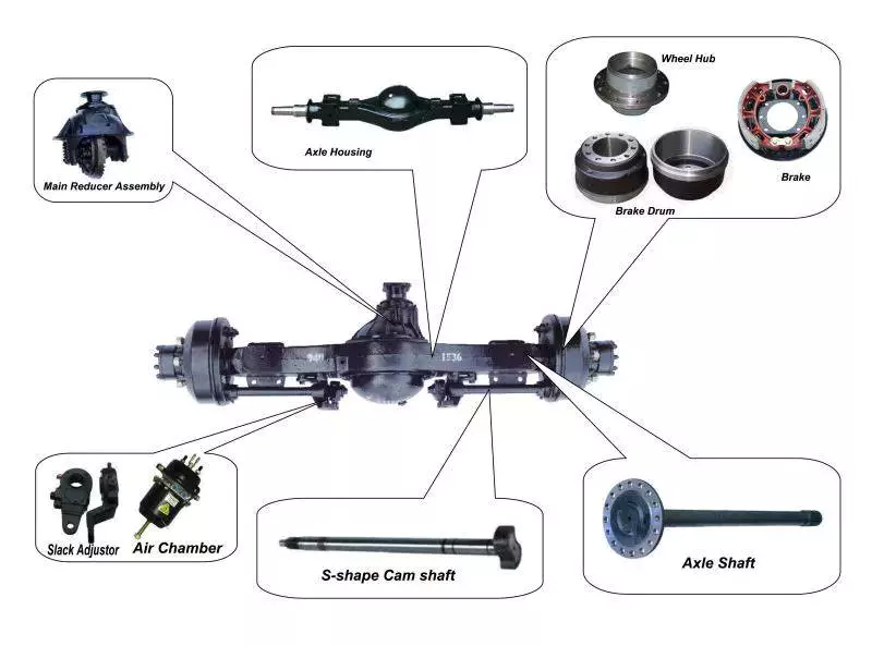
Axles

Drive shaft

A drive shaft is an important part of your vehicle’s drivetrain, which helps to transfer torque from the transmission to the drive wheels. You’ll need to know how it functions in order to properly maintain your car. Fortunately, there are a variety of different parts you can use to upgrade your drive shaft.
In order to improve the performance of your vehicle’s drivetrain, you can replace your existing drive shaft with an upgraded one. These are available in various lengths, so that you can find the right length and fit for your vehicle. Some shafts can even be customized to fit the exact length of your axle.
Generally, short axle shafts are made of solid steel. The longer ones are made of aluminum or carbon fiber. To ensure a smooth and safe ride, they are dynamically balanced to eliminate vibrations. Some models are fitted with giubo joints and universal joints to absorb shock. You can also add flex discs to improve your suspension and dampen the bucking sensation of a drive shaft.
You can tell if your drive shaft needs replacement if you hear a clicking noise while driving. This noise is often audible when the vehicle is turning sharply. You should take your vehicle to a mechanic as soon as you hear this noise, or it could lead to a costly repair. In addition to a clicking noise, your car may also be exhibiting a shuddering or vibrating sensation. If you’re experiencing any of these symptoms, you should take your car in for a checkup by an ASE certified technician. If you ignore these warnings, your car’s drive shaft could separate, causing you a lot of damage.
The drive shaft is attached to the axle flange by a drive shaft bolt. This is an important part of the drivetrain because it’s the only point where the drive shaft will connect to the axle. If the bolt is too long, it could be vulnerable to damage if the washers don’t fit tightly. The drive shaft socket yoke can also be easily damaged when you loosen the bolt.
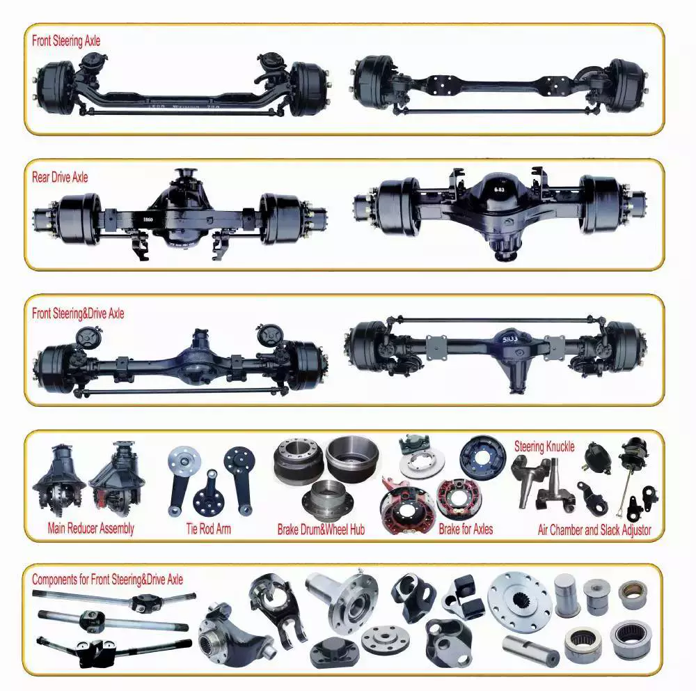
Axles

U-joint

When you replace a u-joint on an axle, you need to take a few things into consideration. One of these considerations is the type of grease you’re going to use. Some of these greases are better than others, and you should always check for a quality grease before you install a new one. A good grease can help to reduce the friction and improve the temperature resistance of the part.
It’s also important to check the u-joint itself. This is the joint between the axle shaft and the wheel. If it’s not functioning properly, it could cause further problems. You should inspect the u-joint every time you change the oil in your vehicle. You can test its lubrication by pressing on the tire with a pry bar or axle stands. You can also try turning the steering wheel fully to test if the joint is loose.
A u-joint failure can leave your car inoperable, which can make driving a risky proposition. If the drive shaft loosens and falls to the ground, you could lose control of your car and risk being stranded. In some severe cases, the front of the driveshaft can even drop to the ground and lift the rear of the car, pushing the car sideways. It’s vital to check u-joints regularly, as failure of the u-joint can cause costly and frustrating car repairs.
When you notice a bad universal joint, you should consider getting it replaced immediately. The most common symptom of a bad u-joint is a clunking sound during acceleration and deceleration. You may also hear vibrations when the u-joint becomes worn and you drive the car. If you notice these symptoms, contact a qualified technician to perform a proper diagnosis.
China Factory price heavy machine transport custom 2 tri axles 4axles large loading capacity low bed trailer     wheel and axleChina Factory price heavy machine transport custom 2 tri axles 4axles large loading capacity low bed trailer     wheel and axle
editor by czh

China wholesaler OEM Custom Steel High Precision Washing Machine Electric Motor Long Shaft with high quality

Product Description

1. Description
 

Product name

304 stainless steel shaft

Material 

Stainless Steel,Aluminum,Brass, Bronze,Carbon steel and ect. environmental protection material.

Size 

 Customized according to your drawing.

Services

OEM, design, customized

Tolerance 

+/-0.01mm to +/-0.005mm

Surface treatment

Passivation

*Polishing

*Anodizing

*Sand blasting

*Electroplating(color, blue, white, black zinc, Ni, Cr, tin, copper, silver)

*Black oxide coating

*Heat-disposing

*Hot-dip galvanizing

*Rust preventive oil

MOQ

1 piece Copper bushing

Samples

We can make sample within 7days free of charge

Certificate

ISO9001:2015  cnc machining turning parts shaft

Payment Terms

Bank Transfer;Western Union; Paypal ; Payoneer, Alibaba Trade Assurance30% deposit & balance before shipping.

Delivery time

Within 15-20 workdays after deposit or payment received

Shipping Port

HangZhou  304 stainless steel shaft

2. Main Motor Shafts

3. Work Flow

4. Application

5. About US


The Functions of Splined Shaft Bearings

Splined shafts are the most common types of bearings for machine tools. They are made of a wide variety of materials, including metals and non-metals such as Delrin and nylon. They are often fabricated to reduce deflection. The tooth profile will become deformed with time, as the shaft is used over a long period of time. Splined shafts are available in a huge range of materials and lengths.

Functions

Splined shafts are used in a variety of applications and industries. They are an effective anti-rotational device, as well as a reliable means of transmitting torque. Other types of shafts are available, including key shafts, but splines are the most convenient for transmitting torque. The following article discusses the functions of splines and why they are a superior choice. Listed below are a few examples of applications and industries in which splines are used.
Splined shafts can be of several styles, depending on the application and mechanical system in question. The differences between splined shaft styles include the design of teeth, overall strength, transfer of rotational concentricity, sliding ability, and misalignment tolerance. Listed below are a few examples of splines, as well as some of their benefits. The difference between these styles is not mutually exclusive; instead, each style has a distinct set of pros and cons.
A splined shaft is a cylindrical shaft with teeth or ridges that correspond to a specific angular position. This allows a shaft to transfer torque while maintaining angular correspondence between tracks. A splined shaft is defined as a cylindrical member with several grooves cut into its circumference. These grooves are equally spaced around the shaft and form a series of projecting keys. These features give the shaft a rounded appearance and allow it to fit perfectly into a grooved cylindrical member.
While the most common applications of splines are for shortening or extending shafts, they can also be used to secure mechanical assemblies. An “involute spline” spline has a groove that is wider than its counterparts. The result is that a splined shaft will resist separation during operation. They are an ideal choice for applications where deflection is an issue.
A spline shaft’s radial torsion load distribution is equally distributed, unless a bevel gear is used. The radial torsion load is evenly distributed and will not exert significant load concentration. If the spline couplings are not aligned correctly, the spline connection can fail quickly, causing significant fretting fatigue and wear. A couple of papers discuss this issue in more detail.
splineshaft

Types

There are many different types of splined shafts. Each type features an evenly spaced helix of grooves on its outer surface. These grooves are either parallel or involute. Their shape allows them to be paired with gears and interchange rotary and linear motion. Splines are often cold-rolled or cut. The latter has increased strength compared to cut spines. These types of shafts are commonly used in applications requiring high strength, accuracy, and smoothness.
Another difference between internal and external splined shafts lies in the manufacturing process. The former is made of wood, while the latter is made of steel or a metal alloy. The process of manufacturing splined shafts involves cutting furrows into the surface of the material. Both processes are expensive and require expert skill. The main advantage of splined shafts is their adaptability to a wide range of applications.
In general, splined shafts are used in machinery where the rotation is transferred to an internal splined member. This member can be a gear or some other rotary device. These types of shafts are often packaged together as a hub assembly. Cleaning and lubricating are essential to the life of these components. If you’re using them on a daily basis, you’ll want to make sure to regularly inspect them.
Crowned splines are usually involute. The teeth of these splines form a spiral pattern. They are used for smaller diameter shafts because they add strength. Involute splines are also used on instrument drives and valve shafts. Serration standards are found in the SAE. Both kinds of splines can also contain a ball bearing for high torque. The difference between the 2 types of splines is the number of teeth on the shaft.
Internal splines have many advantages over external ones. For example, an internal spline shaft can be made using a grinding wheel instead of a CNC machine. It also uses a more accurate and economical process. Furthermore, it allows for a shorter manufacturing cycle, which is essential when splining high-speed machines. In addition, it stabilizes the relative phase between the spline and thread.
splineshaft

Manufacturing methods

There are several methods used to fabricate a splined shaft. Key and splined shafts are constructed from 2 separate parts that are shaped in a synchronized manner to transfer torque uniformly. Hot rolling is 1 method, while cold rolling utilizes low temperatures to form metal. Both methods enhance mechanical properties, surface finishes, and precision. The advantage of cold rolling is its cost-effectiveness.
Cold forming is 1 method, as well as machining and assembling. Cold forming is a unique process that allows the spline to be shaped to the desired shape. The resulting shape provides maximum contact area and torsional strength. Standard splines are available in standard sizes, but custom lengths can also be ordered. CZPT offers various auxiliary equipment, such as mating sleeves and flanged bushings.
Cold forging is another method. This method produces long splined shafts that are used in automobile propellers. After the spline portion is cut out, it is worked on in a hobbing machine. Work hardening enhances the root strength of the splined portion. It can be used for bearings, gears, and other mechanical components. Listed below are the manufacturing methods for splined shafts.
Parallel splines are the simplest of the splined shaft manufacturing methods. Parallel splines are usually welded to shafts, while involute splines are made of metal or non-metals. Splines are available in a wide variety of lengths and materials. The process is usually accompanied by a process called milling. The workpiece rotates to produce the serrated surface.
Splines are internal or external grooves in a splined shaft. They work in combination with keyways to transfer torque. Male and female splines are used in gears. Female and male splines correspond to 1 another to ensure proper angular correspondence. Involute splines have more surface area and thus are stronger than external splines. Moreover, they help the shaft fit into a grooved cylindrical member without misalignment.
A variety of other methods of manufacturing a splined shaft can be used to produce a splined shaft. Spline shafts can be produced using broaching and shaping, 2 precision machining methods. Broaching uses a metal tool with successively larger teeth to remove metal and create ridges and holes in the surface of a material. However, this process is expensive and requires special expertise.
splineshaft

Applications

The splined shaft is a mechanical component with a helix-like shape formed by the equal spacing of grooves in a circular ring. The splines can either have parallel or involute sides. The splines minimize stress concentration in stationary joints and can be used in both rotary and linear motion. In some cases, splines are rolled rather than cut. The latter is more durable than cut splines and is often used in applications requiring high strength, accuracy, and smooth finish.
Splined shafts are commonly made of carbon steel. This alloy steel has a low carbon content, making it easy to work with. Carbon steel is a great choice for splines because it is malleable. Generally, high-quality carbon steel provides a consistent motion. Steel alloys are also available that contain nickel, chromium, copper, and other metals. If you’re unsure of the right material for your application, you can consult a spline chart.
Splines are a versatile mechanical component. They are easy to cut and fit. Splines can be internal or external, with teeth positioned at equal intervals on both sides of the shaft. This allows the shaft to engage with the hub around the entire circumference of the hub. It also increases load capacity by creating a constant multiple-tooth point of contact with the hub. For this reason, they’re used extensively in rotary and linear motion.
Splined shafts are used in a wide variety of industries. CZPT Inc. offers custom and standard splined shafts for a variety of applications. When choosing a splined shaft for a specific application, consider the surrounding mated components, torque requirements, and size requirements. These 3 factors will make it the ideal choice for your rotary equipment. And you’ll be pleased with the end result!
There are many types of splines and their applications are endless. They transfer torque and angular misalignment between parts, and they also enable the axial rotation of assembled components. Therefore, splines are an essential component of machinery and are used in a wide range of applications. This type of shaft can be found in various types of machines, from household appliances to industrial machinery. So, the next time you’re looking for a splined shaft, make sure you look for a splined one.

China wholesaler OEM Custom Steel High Precision Washing Machine Electric Motor Long Shaft     with high qualityChina wholesaler OEM Custom Steel High Precision Washing Machine Electric Motor Long Shaft     with high quality

China wholesaler CE Certificate Tk 100HP Farm Machine Mini Tractor Like John Deere 4weel CZPT with Agriculture Power Tiller Agricultural Machinery for Farm with Free Design Custom

Product Description

Product Description:
TLK TD1004 90-130HP 4WD Wheel Agricultural Farm Tractor China big wheeled farming tractor with ISO Ce Certificate for Sale

Tractor Main Features and Advantages:
1.Equipped famous brand engine showing advanced capacity,low fuel consumption,high economic efficiency.
2. Streamlined appearance design, beautiful and generous.
3.Transmission Case adopt meshed shift and add the gearbox interlock device makes the operation more smoothly,reliable and easier.
4. Double action clutch with disc spring, perform steadily and easy to operate.
5. Fully hydraulic steering system greatly reduced driver’s work strength.
6. Wet disc brake device, reliable brake performance.
7. Separate injection of hydraulic oil, reliable to operate.
8. The lifter with force and position adjustment, with reliable lift.
9. Tractor PTO:
PTO in Double speed : 540/760r/min Optional, For high working efficiency.
PTO shaft of 6 or 8 spline Optional, adaptable for agricultural equipment of all over the world.
10. Big Chassis and Heavy-duty Rear axle for Durable Strong machine.
11. Full series light, ROPS,Sunshade/Canopy, Fan/Heater/Air-conditioned cabin are all available, for more comfortable driving environment


Main Technical Specifications:

Model  TK1004 TK1104 TK1204 TK1304
Type   4×4 Wheeled Type   4×4 Wheeled Type   4×4 Wheeled Type   4×4 Wheeled Type
Dimensions of Tractor (mm)  Length 4480 4480 4480 4480
Width 2050 2050 2050 2050
Height 2570 2570 2570 2570
Tread Front Wheel 1610(usual) 1610(usual) 1610(usual) 1610(usual)
Rear Wheel 1608(usual) 1608(usual) 1608(usual) 1608(usual)
 Wheel Base 2366 2366 2366 2366
Min. Ground Base 405(the bottom of front axle) 405(the bottom of front axle) 405(the bottom of front axle) 405(the bottom of front axle)
Min. Usage Mass(kg) 4200 4200 4200 4200
Engine Model YTO LR4M3Z YTO LR4M3Z YTO LR6B5-23 YTO LR6M5-23
Type Vertical, water cooled and 4-stroke Vertical, water cooled and 4-stroke Vertical, water cooled and 4-stroke Vertical, water cooled and 4-stroke
 Rated Power(kw) 66.2 80.8 88.2 95.6
Rated Rev.(r/min) 2300 2300 2300 2300
 Fuel Diesel Oil Diesel Oil Diesel Oil  Diesel Oil
 Tire Front Wheel 12.4-24 12.4-24 12.4-24 12.4-24
Rear Wheel 16.9-34 16.9-34 16.9-34 16.9-34
 Clutch Dry-friction, single disc and 2 stage Dry-friction, single disc and 2 stage Dry-friction, single disc and 2 stage Dry-friction, single disc and 2 stage
Steering  Hydraulic type  Hydraulic type  Hydraulic type  Hydraulic type
Transmission Box 4×(2+1)×2 Composed 4×(2+1)×2 Composed 4×(2+1)×2 Composed 4×(2+1)×2 Composed
 Suspension Type Post Positioned Tri-point Suspension Catalogue 2 or 3  (optional) Post Positioned Tri-point Suspension Catalogue 2 or 3 (optional) Post Positioned Tri-point Suspension Catalogue 2 or 3 (optional) Post Positioned Tri-point Suspension Catalogue 2 or 3 (optional)
PTO Type and Rev.(r/min) Post-position, independent,
760/850 or 540/1000 or 540/760 (optioanl)
Post-position, independent,
760/850 or 540/1000 or 540/760 (optioanl)
Post-position, independent,
760/1000 or 540/1000 or 540/760 (optioanl)
Post-position, independent,
760/1000 or 540/1000 or 540/760 (optioanl)
Spline Size I38 Rectangle Spline with 8 teeth I38 Rectangle Spline with 8 teeth I38 Rectangle Spline with 8 teeth I38 Rectangle Spline with 8 teeth

Technology & Innovation:

WeiFang Telake has established a professional R & D team, realized the self-control ability of core components by integrating the industry’s
advantageous resources, built a stable quality control system.
Invested tens millions to introduce intelligent mechanization total production line, automatic chassis production line, gearbox processing line and welding
robots, processing centers and other advanced production lines and equipment, to achieve an annual production capacity of 30,000 tractors.

/////////////////////////////////////////////////////////////////////////////////////////////////////////////////////////////////////////////////////////////////////

Packaging & Delivery:
-Delivery time:20- 30 days.

/////////////////////////////////////////////////////////////////////////////////////////////////////////////////////////////////////////////////////////////////////

Certifications:

Common problems
(1) Are you a manufacturing factory or a trading company?
We are a factory with 20 years of professional production experience in the field of 25hp-240hp tractors, located in HangZhou City, ZheJiang Province, China. Our factory has passed ISO9001, CCC, CE, SGS and BV certification. We also have a quality control department to purchase products for customers. This is why the price of our tractors is so reasonable.
(2) Can we print the logo or company name on your product or packaging?
of course. Your logo can be printed on your product by embossing, self-adhesive or silk-screen printing.
(3) About the price
The price is negotiable. It can be changed according to the options or packaging of the tractor.
(4) Regarding payment or other issues
We accept LC, TT, if you have other questions, please email me or chat with me directly.
Contact
Welcome to our factory
Adhere to the business tenet of “Integrity-based, Quality First”, and wholeheartedly provide you with the best products and wholehearted service. We actively cooperate with research institutions and multinational companies to achieve continuous innovation. HangZhou Telake Agricultural Equipment CO.,LTD welcomes domestic and foreign customers to visit and guide!
HangZhou Telake Agricultural Equipment CO.,LTD
Adress: East of Xihu (West Lake) Dis. Road,South of Cailin Road,Xihu (West Lake) Dis. Economic District,HangZhou,ZheJiang ,China


What Are the Advantages of a Splined Shaft?

If you are looking for the right splined shaft for your machine, you should know a few important things. First, what type of material should be used? Stainless steel is usually the most appropriate choice, because of its ability to offer low noise and fatigue failure. Secondly, it can be machined using a slotting or shaping machine. Lastly, it will ensure smooth motion. So, what are the advantages of a splined shaft?
Stainless steel is the best material for splined shafts

When choosing a splined shaft, you should consider its hardness, quality, and finish. Stainless steel has superior corrosion and wear resistance. Carbon steel is another good material for splined shafts. Carbon steel has a shallow carbon content (about 1.7%), which makes it more malleable and helps ensure smooth motion. But if you’re not willing to spend the money on stainless steel, consider other options.
There are 2 main types of splines: parallel splines and crowned splines. Involute splines have parallel grooves and allow linear and rotary motion. Helical splines have involute teeth and are oriented at an angle. This type allows for many teeth on the shaft and minimizes the stress concentration in the stationary joint.
Large evenly spaced splines are widely used in hydraulic systems, drivetrains, and machine tools. They are typically made from carbon steel (CR10) and stainless steel (AISI 304). This material is durable and meets the requirements of ISO 14-B, formerly DIN 5463-B. Splined shafts are typically made of stainless steel or C45 steel, though there are many other materials available.
Stainless steel is the best material for a splined shaft. This metal is also incredibly affordable. In most cases, stainless steel is the best choice for these shafts because it offers the best corrosion resistance. There are many different types of splined shafts, and each 1 is suited for a particular application. There are also many different types of stainless steel, so choose stainless steel if you want the best quality.
For those looking for high-quality splined shafts, CZPT Spline Shafts offer many benefits. They can reduce costs, improve positional accuracy, and reduce friction. With the CZPT TFE coating, splined shafts can reduce energy and heat buildup, and extend the life of your products. And, they’re easy to install – all you need to do is install them.
splineshaft

They provide low noise, low wear and fatigue failure

The splines in a splined shaft are composed of 2 main parts: the spline root fillet and the spline relief. The spline root fillet is the most critical part, because fatigue failure starts there and propagates to the relief. The spline relief is more susceptible to fatigue failure because of its involute tooth shape, which offers a lower stress to the shaft and has a smaller area of contact.
The fatigue life of splined shafts is determined by measuring the S-N curve. This is also known as the Wohler curve, and it is the relationship between stress amplitude and number of cycles. It depends on the material, geometry and way of loading. It can be obtained from a physical test on a uniform material specimen under a constant amplitude load. Approximations for low-alloy steel parts can be made using a lower-alloy steel material.
Splined shafts provide low noise, minimal wear and fatigue failure. However, some mechanical transmission elements need to be removed from the shaft during assembly and manufacturing processes. The shafts must still be capable of relative axial movement for functional purposes. As such, good spline joints are essential to high-quality torque transmission, minimal backlash, and low noise. The major failure modes of spline shafts include fretting corrosion, tooth breakage, and fatigue failure.
The outer disc carrier spline is susceptible to tensile stress and fatigue failure. High customer demands for low noise and low wear and fatigue failure makes splined shafts an excellent choice. A fractured spline gear coupling was received for analysis. It was installed near the top of a filter shaft and inserted into the gearbox motor. The service history was unknown. The fractured spline gear coupling had longitudinally cracked and arrested at the termination of the spline gear teeth. The spline gear teeth also exhibited wear and deformation.
A new spline coupling method detects fault propagation in hollow cylindrical splined shafts. A spline coupling is fabricated using an AE method with the spline section unrolled into a metal plate of the same thickness as the cylinder wall. In addition, the spline coupling is misaligned, which puts significant concentration on the spline teeth. This further accelerates the rate of fretting fatigue and wear.
A spline joint should be lubricated after 25 hours of operation. Frequent lubrication can increase maintenance costs and cause downtime. Moreover, the lubricant may retain abrasive particles at the interfaces. In some cases, lubricants can even cause misalignment, leading to premature failure. So, the lubrication of a spline coupling is vital in ensuring proper functioning of the shaft.
The design of a spline coupling can be optimized to enhance its wear resistance and reliability. Surface treatments, loads, and rotation affect the friction properties of a spline coupling. In addition, a finite element method was developed to predict wear of a floating spline coupling. This method is feasible and provides a reliable basis for predicting the wear and fatigue life of a spline coupling.
splineshaft

They can be machined using a slotting or shaping machine

Machines can be used to shape splined shafts in a variety of industries. They are useful in many applications, including gearboxes, braking systems, and axles. A slotted shaft can be manipulated in several ways, including hobbling, broaching, and slotting. In addition to shaping, splines are also useful in reducing bar diameter.
When using a slotting or shaping machine, the workpiece is held against a pedestal that has a uniform thickness. The machine is equipped with a stand column and limiting column (Figure 1), each positioned perpendicular to the upper surface of the pedestal. The limiting column axis is located on the same line as the stand column. During the slotting or shaping process, the tool is fed in and out until the desired space is achieved.
One process involves cutting splines into a shaft. Straddle milling, spline shaping, and spline cutting are 2 common processes used to create splined shafts. Straddle milling involves a fixed indexing fixture that holds the shaft steady, while rotating milling cutters cut the groove in the length of the shaft. Several passes are required to ensure uniformity throughout the spline.
Splines are a type of gear. The ridges or teeth on the drive shaft mesh with grooves in the mating piece. A splined shaft allows the transmission of torque to a mate piece while maximizing the power transfer. Splines are used in heavy vehicles, construction, agriculture, and massive earthmoving machinery. Splines are used in virtually every type of rotary motion, from axles to transmission systems. They also offer better fatigue life and reliability.
Slotting or shaping machines can also be used to shape splined shafts. Slotting machines are often used to machine splined shafts, because it is easier to make them with these machines. Using a slotting or shaping machine can result in splined shafts of different sizes. It is important to follow a set of spline standards to ensure your parts are manufactured to the highest standards.
A milling machine is another option for producing splined shafts. A spline shaft can be set up between 2 centers in an indexing fixture. Two side milling cutters are mounted on an arbor and a spacer and shims are inserted between them. The arbor and cutters are then mounted to a milling machine spindle. To make sure the cutters center themselves over the splined shaft, an adjustment must be made to the spindle of the machine.
The machining process is very different for internal and external splines. External splines can be broached, shaped, milled, or hobbed, while internal splines cannot. These machines use hard alloy, but they are not as good for internal splines. A machine with a slotting mechanism is necessary for these operations.

China wholesaler CE Certificate Tk 100HP Farm Machine Mini Tractor Like John Deere 4weel CZPT with Agriculture Power Tiller Agricultural Machinery for Farm     with Free Design CustomChina wholesaler CE Certificate Tk 100HP Farm Machine Mini Tractor Like John Deere 4weel CZPT with Agriculture Power Tiller Agricultural Machinery for Farm     with Free Design Custom

China Custom Durable Farm Machine Dq904 90HP 4WD Farm Tractor with Rops for Sale with high quality

Product Description

Durable farm machine DQ904 90HP 4WD Farm Tractor with ROPS for sale

Tractor Main Features and Advantages:
1.Equipped famous brand engine showing advanced capacity,low fuel consumption,high economic efficiency.
2. Streamlined appearance design, beautiful and generous.
3.Transmission Case adopt meshed shift and add the gearbox interlock device makes the operation more smoothly,reliable and easier.
4. Double action clutch with disc spring, perform steadily and easy to operate.
5. Fully hydraulic steering system greatly reduced driver’s work strength.
6. Wet disc brake device, reliable brake performance.
7. Separate injection of hydraulic oil, reliable to operate.
8. The lifter with force and position adjustment, with reliable lift.
9. Tractor PTO:
PTO in Double speed : 540/760r/min Optional, For high working efficiency.
PTO shaft of 6 or 8 spline Optional, adaptable for agricultural equipment of all over the world.
10. Big Chassis and Heavy-duty Rear axle for Durable Strong machine.
11. Full series light, ROPS,Sunshade/Canopy, Fan/Heater/Air-conditioned cabin are all available, for more comfortable driving environment. 

Tractor Main specificaiton and Technical parameters:

Model DQ900 DQ904 DQ950 DQ954
Drive type  4×2 4×4 4×2 4×4
Engine
Engine type YTO or CZPT brand, 4 or 6 cylinder diesel engine
Capacity of fuel tank(L) 150 150 150 150
Rated speed (r/min) 2300
Engine power at rated speed(kw/hp) 66.2kw/90HP 69.8kw/95HP
Transmission
Clutch Dry, dual-stage type
PTO Speed (rpm) 540/1000 or 760/1000
Gearshift 8F+4R/16F+8R(optional)/8F+8R(optional)
Hydraulic system
Hydraulic output valve 2-Group (optional)
Three point linkage 
Category of 3-point link Category II
Lifting force (at point of 610mm)KN >15 >16 >15 >16
Technical parameter
Dimension (LxWxH) (mm) 4593x2050x2810
Wheel base(mm) 2362 2195 2362 2195
Track base(mm) front wheel 1485 1610 1485 1610
Track base(mm) rear wheel 1620
The smallest clearance(mm) 476 379 476 379
Front tyre 6.5-20 11.2-24 6.5-20 11.2-24
Rear tyre 16.9-34(common)/18.4-30(optional)
Optional Configurations
Common cabin with Fan; Heater cabin; AC cabin; ROPS; Canopy (Sunshade); 8F+8R shuttle gearshift, 16F+4R creeper gearshift, 2-Group Hydraulic output valve; Front ballast, Rear ballast; Paddy tire, 18.4-30 big rear tire, 6 cylinder diesel engine, Heavy-duty rear, Air brake, Swing draw bar
Loading Quantity/40HC 3 Sets in Nude packing for CBU shipping

DQ904 90HP 4WD Tractor details  show :

DQ904 90HP 4WD Tractor have different configurations for choose :


Advance Manufacutring Line:

Tractor Packing and Loading container for Delivering goods :

Perfect after-sale service for both Distributors and Private customers:

Please contact us if you have any demand for our Product  :


Best price will be quoted for you as soon as receive your Requirement !

How to Calculate Stiffness, Centering Force, Wear and Fatigue Failure of Spline Couplings

There are various types of spline couplings. These couplings have several important properties. These properties are: Stiffness, Involute splines, Misalignment, Wear and fatigue failure. To understand how these characteristics relate to spline couplings, read this article. It will give you the necessary knowledge to determine which type of coupling best suits your needs. Keeping in mind that spline couplings are usually spherical in shape, they are made of steel.
splineshaft

Involute splines

An effective side interference condition minimizes gear misalignment. When 2 splines are coupled with no spline misalignment, the maximum tensile root stress shifts to the left by 5 mm. A linear lead variation, which results from multiple connections along the length of the spline contact, increases the effective clearance or interference by a given percentage. This type of misalignment is undesirable for coupling high-speed equipment.
Involute splines are often used in gearboxes. These splines transmit high torque, and are better able to distribute load among multiple teeth throughout the coupling circumference. The involute profile and lead errors are related to the spacing between spline teeth and keyways. For coupling applications, industry practices use splines with 25 to 50-percent of spline teeth engaged. This load distribution is more uniform than that of conventional single-key couplings.
To determine the optimal tooth engagement for an involved spline coupling, Xiangzhen Xue and colleagues used a computer model to simulate the stress applied to the splines. The results from this study showed that a “permissible” Ruiz parameter should be used in coupling. By predicting the amount of wear and tear on a crowned spline, the researchers could accurately predict how much damage the components will sustain during the coupling process.
There are several ways to determine the optimal pressure angle for an involute spline. Involute splines are commonly measured using a pressure angle of 30 degrees. Similar to gears, involute splines are typically tested through a measurement over pins. This involves inserting specific-sized wires between gear teeth and measuring the distance between them. This method can tell whether the gear has a proper tooth profile.
The spline system shown in Figure 1 illustrates a vibration model. This simulation allows the user to understand how involute splines are used in coupling. The vibration model shows 4 concentrated mass blocks that represent the prime mover, the internal spline, and the load. It is important to note that the meshing deformation function represents the forces acting on these 3 components.
splineshaft

Stiffness of coupling

The calculation of stiffness of a spline coupling involves the measurement of its tooth engagement. In the following, we analyze the stiffness of a spline coupling with various types of teeth using 2 different methods. Direct inversion and blockwise inversion both reduce CPU time for stiffness calculation. However, they require evaluation submatrices. Here, we discuss the differences between these 2 methods.
The analytical model for spline couplings is derived in the second section. In the third section, the calculation process is explained in detail. We then validate this model against the FE method. Finally, we discuss the influence of stiffness nonlinearity on the rotor dynamics. Finally, we discuss the advantages and disadvantages of each method. We present a simple yet effective method for estimating the lateral stiffness of spline couplings.
The numerical calculation of the spline coupling is based on the semi-analytical spline load distribution model. This method involves refined contact grids and updating the compliance matrix at each iteration. Hence, it consumes significant computational time. Further, it is difficult to apply this method to the dynamic analysis of a rotor. This method has its own limitations and should be used only when the spline coupling is fully investigated.
The meshing force is the force generated by a misaligned spline coupling. It is related to the spline thickness and the transmitting torque of the rotor. The meshing force is also related to the dynamic vibration displacement. The result obtained from the meshing force analysis is given in Figures 7, 8, and 9.
The analysis presented in this paper aims to investigate the stiffness of spline couplings with a misaligned spline. Although the results of previous studies were accurate, some issues remained. For example, the misalignment of the spline may cause contact damages. The aim of this article is to investigate the problems associated with misaligned spline couplings and propose an analytical approach for estimating the contact pressure in a spline connection. We also compare our results to those obtained by pure numerical approaches.

Misalignment

To determine the centering force, the effective pressure angle must be known. Using the effective pressure angle, the centering force is calculated based on the maximum axial and radial loads and updated Dudley misalignment factors. The centering force is the maximum axial force that can be transmitted by friction. Several published misalignment factors are also included in the calculation. A new method is presented in this paper that considers the cam effect in the normal force.
In this new method, the stiffness along the spline joint can be integrated to obtain a global stiffness that is applicable to torsional vibration analysis. The stiffness of bearings can also be calculated at given levels of misalignment, allowing for accurate estimation of bearing dimensions. It is advisable to check the stiffness of bearings at all times to ensure that they are properly sized and aligned.
A misalignment in a spline coupling can result in wear or even failure. This is caused by an incorrectly aligned pitch profile. This problem is often overlooked, as the teeth are in contact throughout the involute profile. This causes the load to not be evenly distributed along the contact line. Consequently, it is important to consider the effect of misalignment on the contact force on the teeth of the spline coupling.
The centre of the male spline in Figure 2 is superposed on the female spline. The alignment meshing distances are also identical. Hence, the meshing force curves will change according to the dynamic vibration displacement. It is necessary to know the parameters of a spline coupling before implementing it. In this paper, the model for misalignment is presented for spline couplings and the related parameters.
Using a self-made spline coupling test rig, the effects of misalignment on a spline coupling are studied. In contrast to the typical spline coupling, misalignment in a spline coupling causes fretting wear at a specific position on the tooth surface. This is a leading cause of failure in these types of couplings.
splineshaft

Wear and fatigue failure

The failure of a spline coupling due to wear and fatigue is determined by the first occurrence of tooth wear and shaft misalignment. Standard design methods do not account for wear damage and assess the fatigue life with big approximations. Experimental investigations have been conducted to assess wear and fatigue damage in spline couplings. The tests were conducted on a dedicated test rig and special device connected to a standard fatigue machine. The working parameters such as torque, misalignment angle, and axial distance have been varied in order to measure fatigue damage. Over dimensioning has also been assessed.
During fatigue and wear, mechanical sliding takes place between the external and internal splines and results in catastrophic failure. The lack of literature on the wear and fatigue of spline couplings in aero-engines may be due to the lack of data on the coupling’s application. Wear and fatigue failure in splines depends on a number of factors, including the material pair, geometry, and lubrication conditions.
The analysis of spline couplings shows that over-dimensioning is common and leads to different damages in the system. Some of the major damages are wear, fretting, corrosion, and teeth fatigue. Noise problems have also been observed in industrial settings. However, it is difficult to evaluate the contact behavior of spline couplings, and numerical simulations are often hampered by the use of specific codes and the boundary element method.
The failure of a spline gear coupling was caused by fatigue, and the fracture initiated at the bottom corner radius of the keyway. The keyway and splines had been overloaded beyond their yield strength, and significant yielding was observed in the spline gear teeth. A fracture ring of non-standard alloy steel exhibited a sharp corner radius, which was a significant stress raiser.
Several components were studied to determine their life span. These components include the spline shaft, the sealing bolt, and the graphite ring. Each of these components has its own set of design parameters. However, there are similarities in the distributions of these components. Wear and fatigue failure of spline couplings can be attributed to a combination of the 3 factors. A failure mode is often defined as a non-linear distribution of stresses and strains.

China Custom Durable Farm Machine Dq904 90HP 4WD Farm Tractor with Rops for Sale     with high qualityChina Custom Durable Farm Machine Dq904 90HP 4WD Farm Tractor with Rops for Sale     with high quality

China Good quality Flexible Spiral Vertical Screw Conveyor Machine with Free Design Custom

Product Description

1.Product Details


1.Advantages Of Screw Conveyor:


1.Using high quality steel pipe, the overall rigidity is good.
2.Double pitch blade to reduce the degree of compression in material transportation .
3.It adopts high-quality reducer and heavy-duty design. It has the characteristics of large turning distance and low noise.
4.Universal ball connection is optional to facilitate installation, adjustment and steeling.
5.Equipped with medium suspension bearings and tail bearings of good quality, and easy to install.
6.Adequate spare parts, complete specifications.
7.Commonly used diameter 165,219,273,323,407 large stock,size and angle can be customized according to customer requirements.
8.Standard components, easy to transport.
9.One-time forming of spiral blade,double pitch design ,never plugging.


1.Simple structure, good sealing, easy operation and low power invest cost. 
2.It has the features of small screw diameter, high rotation speed and large capacity, specially suitable for inclined transport. The angle is up to 60 degree. 
3.Widely used in chemical, metallurgy, paper making, and construction industries, etc. 
4.Axle head and conveying spiral adopt spline connection, with features of convenient mounting&disassembling, large load capacity and stability. 
5.All sections of screw conveyor are connected with flange. Also screw blades are integral connection. 
6.Inlet and outlet chutes have many kinds of connections, such as flange, sack, universal joint, etc.

2.Our Company’s Product:

Reducer: an independent part composed of gear drive, worm drive and gear – worm drive enclosed in a rigid shell. It plays the role of matching speed and transferring torque between prime mover and working machine or actuator. It is a kind of relatively precise machinery. The purpose of using it is to reduce the speed and increase the torque. 

Shaft-end Seal: With multi-shaft-end seal in shaft end and avoids cement&mud approaching to shaft end to extend service life of the concrete mixer.
Discharging Device: Hydralic discharging system,with strong drive force and reliable discharging.Discharging door can be opened at any angle,with manual discharging function.The discharging door adopts detachable structure which is convenient for maint.
 

Shaft end seal:Separate seal and bearing, more stable operation, better maintenance, easy replacement, and maintenance;
Discharge mechanism:unloading door is made by tooling and then processed by lathe to eliminate the phenomenon of Carmen; Hydraulic discharge, stable operation.


2.Company Profile

MAHangZhou CZPT METALLURGICAL MACHINE CO.,LTD. is located in the famous steel city HangZhou City, rich iron and steel resources for the development of my company provides a unique advantage, the company is the production and research of various wear-resistant, heat-resistant, shock-resistant alloy castings professional manufacturers; business is characterized by fine, special, unique. Products to the market economy needs throughout the country, each year more than 5,000 tons of various casting products in metallurgical machinery, construction, cement, transportation and other industries widely used. This product its unique properties of various materials to resist wear and tear on the product, as many national key projects of qualified suppliers.

3.Packaging & Delivery

Quick delivery and high efficiency.
Use reinforced packaging for important electronic accessories and wearing parts.
We will carefully calculate the type of space and cabinet needed to minimize the cost to buyers and help them save money.
Port: HangZhou, ZheJiang , ZheJiang , HangZhou, HangZhou

4.Service

Technical files service provided.
Spare parts replacement and repair service provided.
Our Products can be customized according to clients’ different requirement.
Technical support online service provided.

5.After-sale Service

May enjoy the life-long service and technical consultation after you buy our products.
Certain quantity stochastic tool will be provided while delivering goods.
Within 48 hours service will be available according to different regions after received the telephone.
The time of warranty is for a whole year
Promptly provides the fittings according to users’ demands, handles for the user consigns for shipment.
Provides the technology advisory service as necessary.
Please contact me when you have any problems with the plant.

6.Contact


Stiffness and Torsional Vibration of Spline-Couplings

In this paper, we describe some basic characteristics of spline-coupling and examine its torsional vibration behavior. We also explore the effect of spline misalignment on rotor-spline coupling. These results will assist in the design of improved spline-coupling systems for various applications. The results are presented in Table 1.
splineshaft

Stiffness of spline-coupling

The stiffness of a spline-coupling is a function of the meshing force between the splines in a rotor-spline coupling system and the static vibration displacement. The meshing force depends on the coupling parameters such as the transmitting torque and the spline thickness. It increases nonlinearly with the spline thickness.
A simplified spline-coupling model can be used to evaluate the load distribution of splines under vibration and transient loads. The axle spline sleeve is displaced a z-direction and a resistance moment T is applied to the outer face of the sleeve. This simple model can satisfy a wide range of engineering requirements but may suffer from complex loading conditions. Its asymmetric clearance may affect its engagement behavior and stress distribution patterns.
The results of the simulations show that the maximum vibration acceleration in both Figures 10 and 22 was 3.03 g/s. This results indicate that a misalignment in the circumferential direction increases the instantaneous impact. Asymmetry in the coupling geometry is also found in the meshing. The right-side spline’s teeth mesh tightly while those on the left side are misaligned.
Considering the spline-coupling geometry, a semi-analytical model is used to compute stiffness. This model is a simplified form of a classical spline-coupling model, with submatrices defining the shape and stiffness of the joint. As the design clearance is a known value, the stiffness of a spline-coupling system can be analyzed using the same formula.
The results of the simulations also show that the spline-coupling system can be modeled using MASTA, a high-level commercial CAE tool for transmission analysis. In this case, the spline segments were modeled as a series of spline segments with variable stiffness, which was calculated based on the initial gap between spline teeth. Then, the spline segments were modelled as a series of splines of increasing stiffness, accounting for different manufacturing variations. The resulting analysis of the spline-coupling geometry is compared to those of the finite-element approach.
Despite the high stiffness of a spline-coupling system, the contact status of the contact surfaces often changes. In addition, spline coupling affects the lateral vibration and deformation of the rotor. However, stiffness nonlinearity is not well studied in splined rotors because of the lack of a fully analytical model.
splineshaft

Characteristics of spline-coupling

The study of spline-coupling involves a number of design factors. These include weight, materials, and performance requirements. Weight is particularly important in the aeronautics field. Weight is often an issue for design engineers because materials have varying dimensional stability, weight, and durability. Additionally, space constraints and other configuration restrictions may require the use of spline-couplings in certain applications.
The main parameters to consider for any spline-coupling design are the maximum principal stress, the maldistribution factor, and the maximum tooth-bearing stress. The magnitude of each of these parameters must be smaller than or equal to the external spline diameter, in order to provide stability. The outer diameter of the spline must be at least 4 inches larger than the inner diameter of the spline.
Once the physical design is validated, the spline coupling knowledge base is created. This model is pre-programmed and stores the design parameter signals, including performance and manufacturing constraints. It then compares the parameter values to the design rule signals, and constructs a geometric representation of the spline coupling. A visual model is created from the input signals, and can be manipulated by changing different parameters and specifications.
The stiffness of a spline joint is another important parameter for determining the spline-coupling stiffness. The stiffness distribution of the spline joint affects the rotor’s lateral vibration and deformation. A finite element method is a useful technique for obtaining lateral stiffness of spline joints. This method involves many mesh refinements and requires a high computational cost.
The diameter of the spline-coupling must be large enough to transmit the torque. A spline with a larger diameter may have greater torque-transmitting capacity because it has a smaller circumference. However, the larger diameter of a spline is thinner than the shaft, and the latter may be more suitable if the torque is spread over a greater number of teeth.
Spline-couplings are classified according to their tooth profile along the axial and radial directions. The radial and axial tooth profiles affect the component’s behavior and wear damage. Splines with a crowned tooth profile are prone to angular misalignment. Typically, these spline-couplings are oversized to ensure durability and safety.

Stiffness of spline-coupling in torsional vibration analysis

This article presents a general framework for the study of torsional vibration caused by the stiffness of spline-couplings in aero-engines. It is based on a previous study on spline-couplings. It is characterized by the following 3 factors: bending stiffness, total flexibility, and tangential stiffness. The first criterion is the equivalent diameter of external and internal splines. Both the spline-coupling stiffness and the displacement of splines are evaluated by using the derivative of the total flexibility.
The stiffness of a spline joint can vary based on the distribution of load along the spline. Variables affecting the stiffness of spline joints include the torque level, tooth indexing errors, and misalignment. To explore the effects of these variables, an analytical formula is developed. The method is applicable for various kinds of spline joints, such as splines with multiple components.
Despite the difficulty of calculating spline-coupling stiffness, it is possible to model the contact between the teeth of the shaft and the hub using an analytical approach. This approach helps in determining key magnitudes of coupling operation such as contact peak pressures, reaction moments, and angular momentum. This approach allows for accurate results for spline-couplings and is suitable for both torsional vibration and structural vibration analysis.
The stiffness of spline-coupling is commonly assumed to be rigid in dynamic models. However, various dynamic phenomena associated with spline joints must be captured in high-fidelity drivetrain models. To accomplish this, a general analytical stiffness formulation is proposed based on a semi-analytical spline load distribution model. The resulting stiffness matrix contains radial and tilting stiffness values as well as torsional stiffness. The analysis is further simplified with the blockwise inversion method.
It is essential to consider the torsional vibration of a power transmission system before selecting the coupling. An accurate analysis of torsional vibration is crucial for coupling safety. This article also discusses case studies of spline shaft wear and torsionally-induced failures. The discussion will conclude with the development of a robust and efficient method to simulate these problems in real-life scenarios.
splineshaft

Effect of spline misalignment on rotor-spline coupling

In this study, the effect of spline misalignment in rotor-spline coupling is investigated. The stability boundary and mechanism of rotor instability are analyzed. We find that the meshing force of a misaligned spline coupling increases nonlinearly with spline thickness. The results demonstrate that the misalignment is responsible for the instability of the rotor-spline coupling system.
An intentional spline misalignment is introduced to achieve an interference fit and zero backlash condition. This leads to uneven load distribution among the spline teeth. A further spline misalignment of 50um can result in rotor-spline coupling failure. The maximum tensile root stress shifted to the left under this condition.
Positive spline misalignment increases the gear mesh misalignment. Conversely, negative spline misalignment has no effect. The right-handed spline misalignment is opposite to the helix hand. The high contact area is moved from the center to the left side. In both cases, gear mesh is misaligned due to deflection and tilting of the gear under load.
This variation of the tooth surface is measured as the change in clearance in the transverse plain. The radial and axial clearance values are the same, while the difference between the 2 is less. In addition to the frictional force, the axial clearance of the splines is the same, which increases the gear mesh misalignment. Hence, the same procedure can be used to determine the frictional force of a rotor-spline coupling.
Gear mesh misalignment influences spline-rotor coupling performance. This misalignment changes the distribution of the gear mesh and alters contact and bending stresses. Therefore, it is essential to understand the effects of misalignment in spline couplings. Using a simplified system of helical gear pair, Hong et al. examined the load distribution along the tooth interface of the spline. This misalignment caused the flank contact pattern to change. The misaligned teeth exhibited deflection under load and developed a tilting moment on the gear.
The effect of spline misalignment in rotor-spline couplings is minimized by using a mechanism that reduces backlash. The mechanism comprises cooperably splined male and female members. One member is formed by 2 coaxially aligned splined segments with end surfaces shaped to engage in sliding relationship. The connecting device applies axial loads to these segments, causing them to rotate relative to 1 another.

China Good quality Flexible Spiral Vertical Screw Conveyor Machine     with Free Design CustomChina Good quality Flexible Spiral Vertical Screw Conveyor Machine     with Free Design Custom